80S-15贴片机.pdf - 第187页
SIPLACE 80 S/ F/G Service M anual 7 Components Table Edition 04/97 7 - 5 ● Components feeder modules: The feede r module s are c onnected t o the po wer supp ly at the c onnec- tions pa nel of the commu nication s unit :…

7 Components Table SIPLACE 80 S/F/G Service Manual
Edition 04/97
7 - 4
7.1.1.1 Mechanical Design
●
In the SIPLACE 80 S machine the feeder modules are picked up on 2 "changeover components tables"
(table 1 and table 2).
●
These changeover components tables are in each case mounted on a frame which also carries the com-
ponents table power supply (transformer T1), the communications unit, the tape container and the waste
tape container. This unit is designated the "components changeover table" (see Fig. 7.1.2).
●
The "components changeover table" can be lifted by a lift truck and moved out of the machine (for
details on the procedure, see User’s Manual, Section 8).
●
The defined position of the components table with respect to the machine base is ensured by the two dif-
ferently shaped centering pieces on the machine base which when the components table is lowered by the
lift truck move into the locating holes (press fit bushes) of the table (see Fig. 7.1.1). After it has been
placed in position, the components changeover table is held by means of 2 tensioning elements against
the support areas on the left and right of the machine base.
●
Due to the precision of location required, it will not be necessary to check or reposition the track (machine
data) after replacement of the components changeover table.
●
Definition of the locations for the SIPLACE 80 S can be seen in Fig. 7.1.1. Further details will be found for
example in section 5 "Data input" under "Components supply".
●
The feeder modules are in each case connected by locating pins and spherical caps on the components
table (see Fig. 7.1.2) in a defined position and held in place by the magnetic strip.
●
For the use of compressed air feeder modules (feeder modules using compressed air to convey) the
"components table compressed air supply unit" is fitted to the components table and the "pneumatic
components table" to the machine base - both as options (see Fig. 7.1.2).
●
Flap opener and empty tape channel of the each location are screwed down to a rail and then fastened to
the machine base with the aid of this rail (see Fig. 7.1.3).
●
The empty tape cutting unit is mounted with 2 brackets to the machine base - - just like the flap opener,
separate from the components changeover table - (see Fig. 7.1.4).
7.1.1.2 Electrical / Pneumatic Systems
NOTE
An overview of the electrical system of the components changeover table will be found in the circuits folder.
●
The "components changeover table" (see Fig. 7.1.2) has its own power supply (transformer T1, see Fig.
7.1.2) and its own controller (communications unit), which are connected as follows:
–
Components table power supply
→
cable "Power" Y516-W1 or W2
→
mains plug on the righthand
side of the machine base (see Fig. 7.1.1),
–
Communications unit
→
cable "Components table interface" Y559-W1
→
plug X37 (interface right-
hand / lefthand), also on the righthand side of the machine base, see Fig. 7.1.1.
●
Components table-power supply: The transformer T1 is protected at the input end by fuse F1 with 3.16
AT and the 8 VAC and 28 VAC voltages for the communications unit tapped off on the output side.

SIPLACE 80 S/F/G Service Manual 7 Components Table
Edition 04/97
7 - 5
●
Components feeder modules:
The feeder modules are connected to the power supply at the connec-
tions panel of the communications unit:
–
Vibratory feeders, tape feeder modules and compressed air feeder modules are connected directly to
the power outlet socket of the connections panel of the communications unit.
–
Tape feeder modules are supplied with 30 VDC at SIPLACE machines, vibratory feeders with an
adjustable a.c. voltage.
–
The +30 VDC voltage is constantly applied to the corresponding socket of the connections panel, the
a.c. voltage only when the vibratory feeder is activated.
–
The vibration intensity is adjusted by means of the potentiometer rotary button below it.
–
The vibration period is specified by the corresponding data input (at the UNIX line computer, under
"Correction of coordinates").
–
The adapter with built-in potentiometer (vibratory feeder) or the Lemosa-Binder plug (tape feeder
modules) is only required for connection to the external power supply for setting work, for example.
–
The vibrators (vibratory feeders), the tape and compressed air feeder modules and the empty tape
cutting unit are operated by the communications unit while the individual flap openers are actuated by
the board "Flap openers control" (part of the "Flap openers" module).
A precondition for this is that the corresponding command must have been received at the placement
station.
●
Empty tape cutting unit
(see Fig. 7.1.3): connection to the
5.6 bar
compressed air branch (fixed preset
operating pressure) of the compressed air unit, electrical connection via the components table interface
(plug X37 on the righthand side of the machine base) at the corresponding communications unit.
●
Flap opener
(see Fig. 7.1.4): connection to the
2.8 bar
compressed air branch, electrical connection via
the components table interface (plug X37 on the righthand side of the machine base) at the corresponding
communications unit.
●
Components table compressed air supply unit, option
(see Fig. 7.1.5): connection via the "compo-
nents table pneumatic system" (option) to the
5 bar
compressed air branch. The components table com-
pressed air supply unit is used for holding and supplying compressed air to the compressed air feeder
modules.
7 Components Table SIPLACE 80 S/F/G Service Manual
Edition 04/97
7 - 6
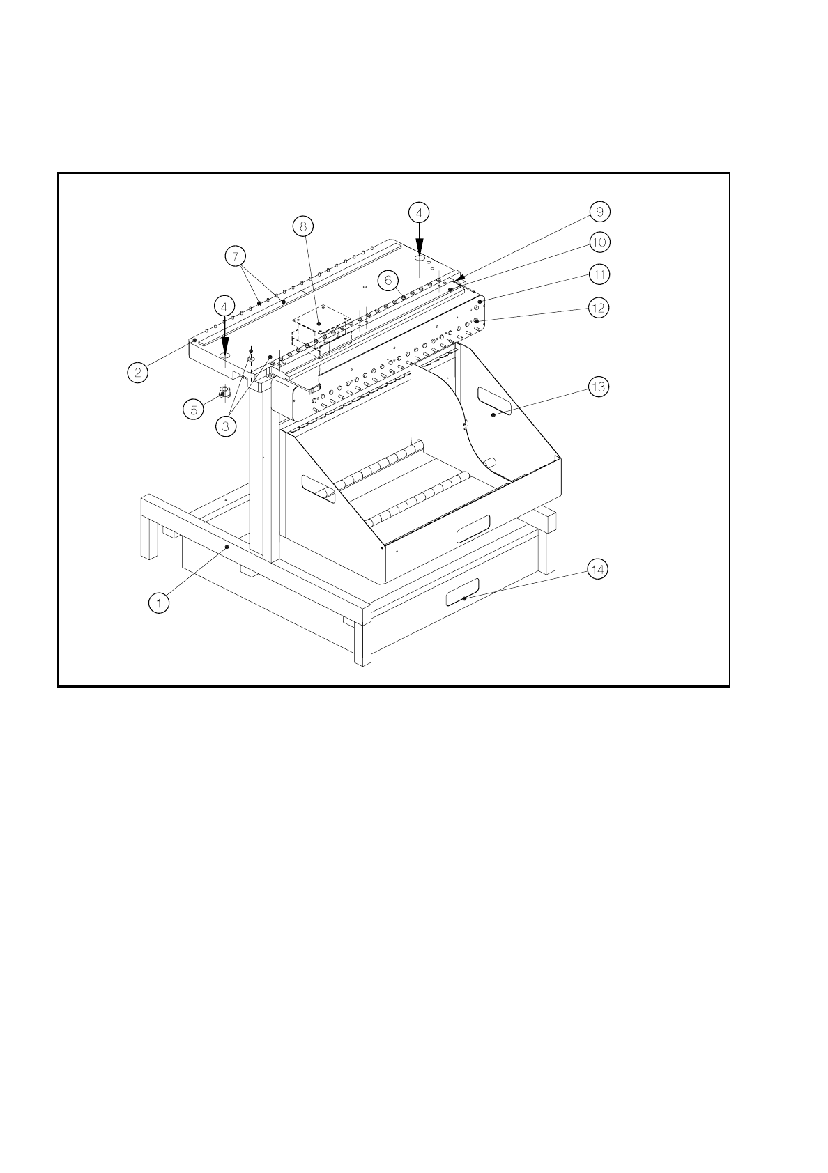
7.1.2 Components Changeover Tables: Structure / Subassemblies
Fig. 7.1.2 Structure of the components changeover tables
Key to Fig. 7.1.2
1 Frame
2 Changeover components table, complete, 20-up
3 Mounting of the changeover components table to the frame (4 socket-head cap screws M8)
4 Locating holes in the changeover components table
5 Centering aids in the machine base
6 Spherical caps for centered positioning of the feeder modules
7 Magnetic block and parallel pins for centered positioning of the feeder modules
8 Transformer of components table (power supply for components table)
9 Compressed air connection for the components table compressed air supply
10 Components table compressed air supply for NITTO feeder (option)
11 Communications unit
12 Connections panel for feeder modules
13 Tape container (holds the tape reels)
14 Waste tape container