80S-15贴片机.pdf - 第188页
7 Components Table S IPLACE 80 S/F/G Servic e Manual Edition 04/97 7 - 6 7.1.2 Components Changeover Tables: St ructure / Subassemblies Fig. 7.1.2 Structure of the components changeover tables Key to Fig. 7.1.2 1 Frame 2…

SIPLACE 80 S/F/G Service Manual 7 Components Table
Edition 04/97
7 - 5
●
Components feeder modules:
The feeder modules are connected to the power supply at the connec-
tions panel of the communications unit:
–
Vibratory feeders, tape feeder modules and compressed air feeder modules are connected directly to
the power outlet socket of the connections panel of the communications unit.
–
Tape feeder modules are supplied with 30 VDC at SIPLACE machines, vibratory feeders with an
adjustable a.c. voltage.
–
The +30 VDC voltage is constantly applied to the corresponding socket of the connections panel, the
a.c. voltage only when the vibratory feeder is activated.
–
The vibration intensity is adjusted by means of the potentiometer rotary button below it.
–
The vibration period is specified by the corresponding data input (at the UNIX line computer, under
"Correction of coordinates").
–
The adapter with built-in potentiometer (vibratory feeder) or the Lemosa-Binder plug (tape feeder
modules) is only required for connection to the external power supply for setting work, for example.
–
The vibrators (vibratory feeders), the tape and compressed air feeder modules and the empty tape
cutting unit are operated by the communications unit while the individual flap openers are actuated by
the board "Flap openers control" (part of the "Flap openers" module).
A precondition for this is that the corresponding command must have been received at the placement
station.
●
Empty tape cutting unit
(see Fig. 7.1.3): connection to the
5.6 bar
compressed air branch (fixed preset
operating pressure) of the compressed air unit, electrical connection via the components table interface
(plug X37 on the righthand side of the machine base) at the corresponding communications unit.
●
Flap opener
(see Fig. 7.1.4): connection to the
2.8 bar
compressed air branch, electrical connection via
the components table interface (plug X37 on the righthand side of the machine base) at the corresponding
communications unit.
●
Components table compressed air supply unit, option
(see Fig. 7.1.5): connection via the "compo-
nents table pneumatic system" (option) to the
5 bar
compressed air branch. The components table com-
pressed air supply unit is used for holding and supplying compressed air to the compressed air feeder
modules.
7 Components Table SIPLACE 80 S/F/G Service Manual
Edition 04/97
7 - 6
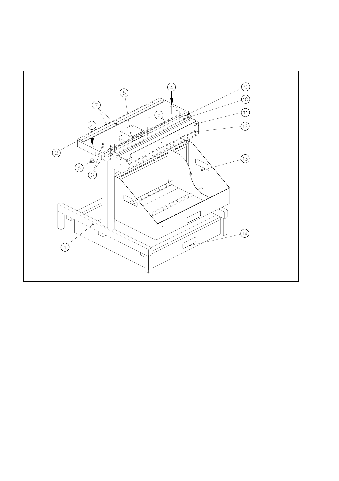
7.1.2 Components Changeover Tables: Structure / Subassemblies
Fig. 7.1.2 Structure of the components changeover tables
Key to Fig. 7.1.2
1 Frame
2 Changeover components table, complete, 20-up
3 Mounting of the changeover components table to the frame (4 socket-head cap screws M8)
4 Locating holes in the changeover components table
5 Centering aids in the machine base
6 Spherical caps for centered positioning of the feeder modules
7 Magnetic block and parallel pins for centered positioning of the feeder modules
8 Transformer of components table (power supply for components table)
9 Compressed air connection for the components table compressed air supply
10 Components table compressed air supply for NITTO feeder (option)
11 Communications unit
12 Connections panel for feeder modules
13 Tape container (holds the tape reels)
14 Waste tape container
SIPLACE 80 S/F/G Service Manual 7 Components Table
Edition 04/97
7 - 7
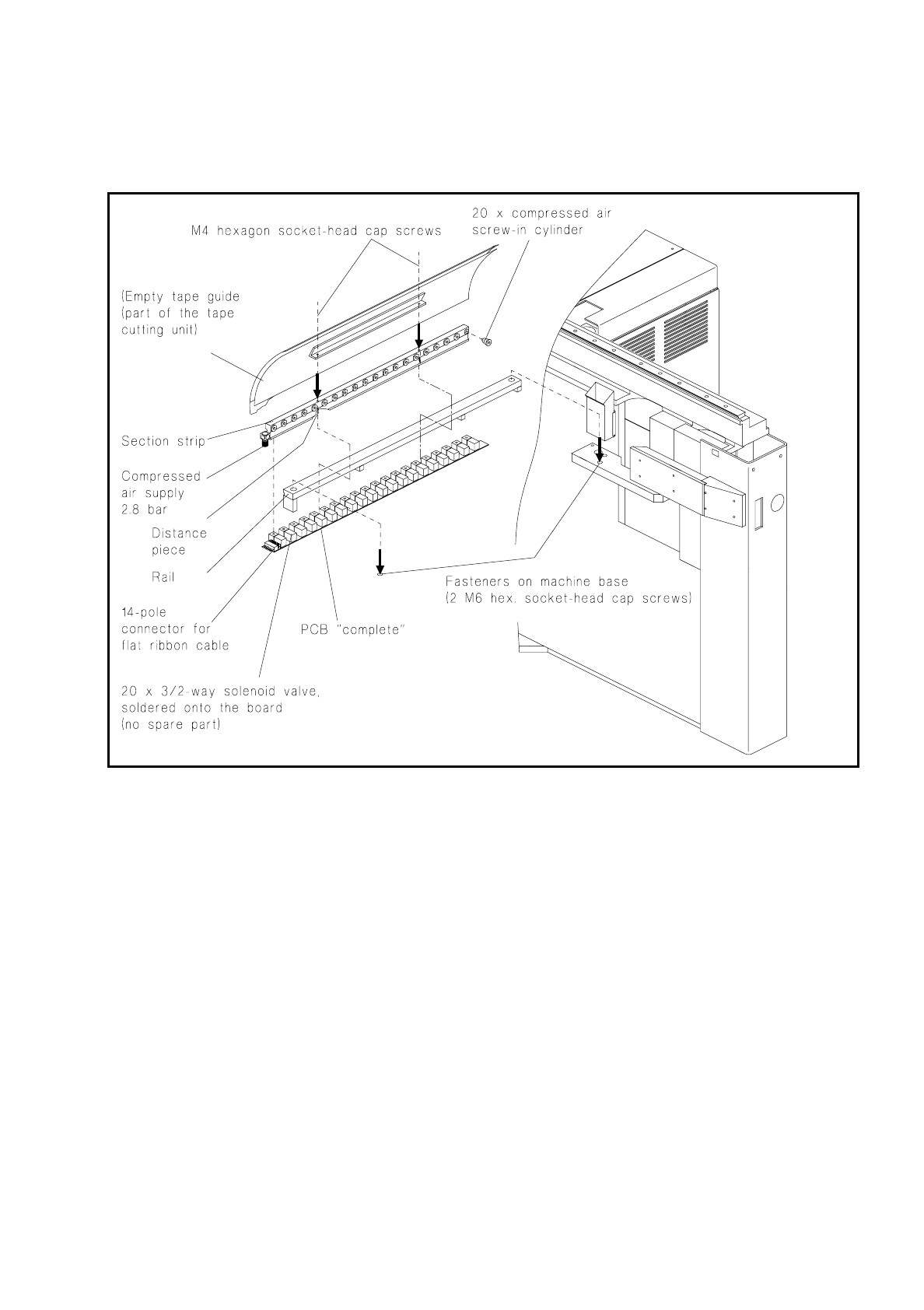
7.1.3 Flap Openers: Structure and Control
Fig. 7.1.3 Flap opener: position, structure and connections
7.1.3.1 Control
Upon reception of the signal (output) from the communications unit the "Flap openers control" board (see Fig.
7.1.3) operates the solenoid valve associated with the location (on the board); this activates the 2.8 bar com-
pressed air circuit, and the flap opener compressed air cylinder extends or retracts.
When the following modules are used the flap opener will be controlled in this way:
–
24/32 mm tape feeder module (44 and 56 mm)
–
8 mm tape feeder module electrical V2, with tape cover (option)
–
linear vibration feeder
Detailed information on the activation of the flap opener in the placement sequence will be found in the User’s
Manual "Feeder Modules".