80S-15贴片机.pdf - 第200页
7 Components Table S IPLACE 80 S/F/G Servic e Manual Edition 04/97 7 - 18 ● Slide th e placem ent hea d by hand over th e board c onveyor (see CAU TION note in s ection 7 .2 „ F ault Char- acteristi cs “ on page 7 - 1 1)…

SIPLACE 80 S/F/G Service Manual 7 Components Table
Edition 04/97
7 - 17
7.3 Components Table Power Supply
DANGER
QQQ
Before you start work on the components table power supply, the components changeover table must be dis-
connected from the mains (mains plug, on the righthand side of the machine base).
Please note with all work in the machine base interior and in particular on the components table power supply
the stricter VDE 0113 safety regulations.
7.3.1 Tools and Spare Parts Required
Auxiliary Measuring and Test Equipment
●
Ohmmeter
Spare Parts
●
Miniature fuse 5x20/T3,16AT, from Item No. 00304938-01
●
Cable: control signals, components table Y558-W1, from Item No. 00300380-06
●
Cable: power, components table Y545-W1, from Item No. 00300379-03
NOTE:
With error message "Communication with table interrupted" the fuse F1 at transformer T1 could be defective.
Carry out preliminary fault location with the aid of the section 7.2 "Fault Characteristics".
Details of the components table power supply will be found in the Overview section, the corresponding circuit
diagrams in the current circuit diagrams folder: diagram 1710460-Y0928-...-L-.../-Y0558-..-L-.../-Y0545-...-L-..
7.3.2 Replacing Fuse F1
●
Select "Abort placement" to return all picked-up components.
DANGER
QQQ
Switch off the machine at the main switch and disconnect it from the power supply.
●
Undo the plug connections of the components changeover table at the machine base on the right beside
the components changeover table (mains and interface connector X37 and if applicable the pneumatic
connection).
●
Open the protective covers and pull cover at the components loading point upwards and away.
7 Components Table SIPLACE 80 S/F/G Service Manual
Edition 04/97
7 - 18
●
Slide the placement head by hand over the board conveyor (see CAUTION note in section 7.2 „Fault Char-
acteristics“ on page 7 - 11).
●
Release the clamping lever and lift and using a lift truck move the components changeover table including
fitted feeder modules carefully out of the machine as described in the User’s Manual.
●
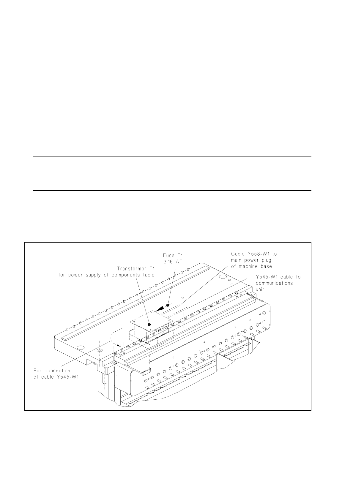
Unscrew and remove the fuse F1 at the transformer T1 (see Fig. 7.3.1).
–
If the fuse is defective, first, where possible, remove the cause of the problem, which should be looked
for on the output side of the transformer:
If necessary, remove the communications unit (see section 7.5 "Communications Unit") and use the
meter at the 5-pin plug (cable of power supply communications unit) to see whether there is a short
circuit in the cable or in the transformer winding. Please observe the following NOTE!
–
If you can correct the short circuit in another way, replace the 3.16 AT fuse.
NOTE
The transformer T1 and / or the cables Y558-W1 and Y545-W1 at the transformer (see Fig. 7.3.1) will be
replaced only by the SMD Service department of Siemens AG.
●
Install the components changeover table back in the machine in the reverse sequence of operations to
removal as described above. Make sure the plug connections (mains plug and X37, and, if applicable,
pneumatic connection) are firmly seated.
●
Switch the machine on and start the placement sequence.
Fig. 7.3.1 Components table power supply: checking and replacing the fuse

SIPLACE 80 S/F/G Service Manual 7 Components Table
Edition 04/97
7 - 19
7.4 Flap Opener (Magazine Openers)
7.4.1 Tools and Spare Parts Required
Tools
●
Screwdriver for socket-head cap screws, set
●
Open-ended spanner SW 7 (for screw-in cylinder)
●
Side-cutting pliers
Auxiliary Measuring and Test Equipment
●
Multimeter, range of measurement 30 VDC
●
Gauge blocks (dimension required: 285.5
±
0.2 mm)
Spare Parts
●
Flap opener SIPLACE 80, from Item No. 00116003-04
●
Adhesive tape
●
Compressed air hose
●
Cable lacing
7.4.2 Fault Location and Correction
NOTE
Error message No. 43 can indicate a fault in the flap opener.
Start fault location by referring to the section 7.2 "Fault Characteristics".
Information on the structure and functioning of the flap opener will be found in the section 7.1 "Overview".
If an individual flap opener is not being activated, the plunger will no longer extend or retract far enough or the
flap openers of an entire location (1 or 3) will not operate, proceed as described below.
7.4.2.1 Checking the Compressed Air Branch and Plug Connections
●
Select "Abort placement" in order to return all of the components picked up at the placement heads in the
course of the following reference run.