80S-15贴片机.pdf - 第206页
7 Components Table S IPLACE 80 S/F/G Servic e Manual Edition 04/97 7 - 24 ● Undo the screws faste ning the cast iron str ip to th e mac hine bas e (2 s ocket-hea d cap screws M6) and with the aid of gau ge block s align …
SIPLACE 80 S/F/G Service Manual 7 Components Table
Edition 04/97
7 - 23
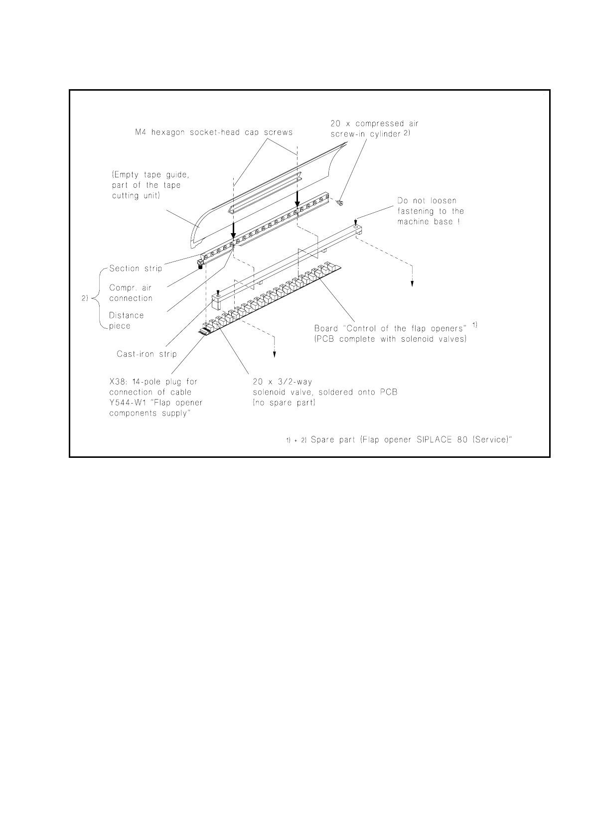
Fig. 7.4.2 Replacing the flap opener (without cast iron strip)
7.4.2.4 Adjusting the Flap Opener relative to the Components Table
The flap opener must in the following cases be aligned with the components table:
–
In the event of a fault, as when the feeder modules are not being correctly operated despite other faults
being excluded, such as restricted movement of the screw-in cylinder (see Fig. 7.4.3) or incorrect adjust-
ment at the feeder module. This will express itself through a fault in components removal or in the tape
cycling (see User’s Manual "Feeder Modules").
–
After refitting the cast iron strip (including flap opener) to the machine base.
●
Adjust the flap opener as follows:
●
Loosen off the strip at little from the machine base (2 socket-head cap screws M6).
7 Components Table SIPLACE 80 S/F/G Service Manual
Edition 04/97
7 - 24
●
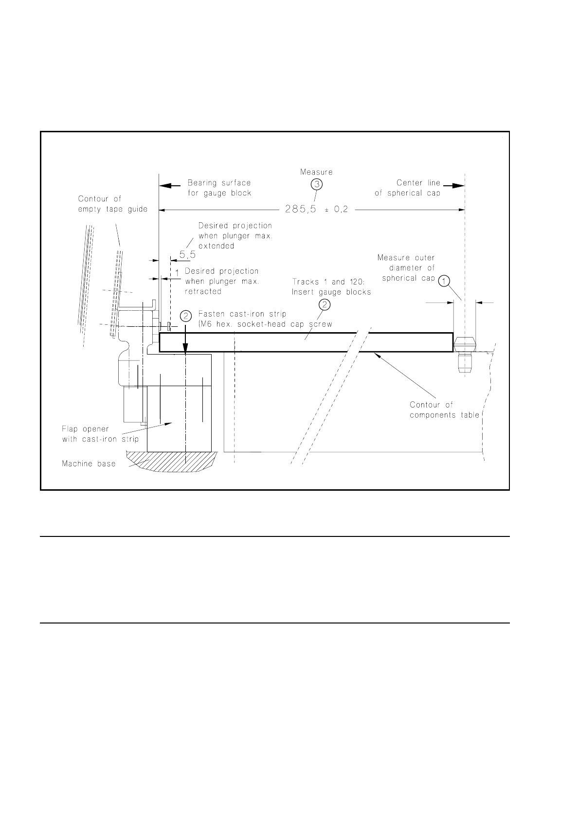
Undo the screws fastening the cast iron strip to the machine base (2 socket-head cap screws M6) and with
the aid of gauge blocks align the flap opener so that the dimension of 285.5
±
0.2 mm can be measured at
both track 1 and track 120. The procedure is shown in Fig. 7.4.3. Screw the strip down tight in this position.
Fig. 7.4.3 Aligning the flap opener including cast iron strip
NOTE:
After adjusting the flap opener you must not forget to align the empty tape cutting device (pressure rod) sym-
metrically with the empty tape channel (see section 7.6.14 "Fitting and Aligning the Empty Tape Cutting Unit
and Empty Tape Channel", under "Fitting and aligning the empty tape channel"). To do this, the components
changeover table has to be removed.

SIPLACE 80 S/F/G Service Manual 7 Components Table
Edition 04/97
7 - 25
7.5 Communications Unit
7.5.1 Tools and Spare Parts Required
Tools
●
Crosstip screwdriver, set
Auxiliary Measuring and Test Equipment
●
Feeder position tester, from Item No. 00304770-03
●
Ohmmeter
Spare Parts
●
Battery, lithium 3.0V 200 mAh DL2430, from Item No. 00314295-01
●
Communications unit 80S, from Item No. 00116013-04
●
Cable: control signals, components table, Y559-W1, from Item No. 00300380-06
●
Miniature fuse 5x20/T3,16A / glass, from Item No. 00304938-04
7.5.2 Fault Location and Correction
NOTE
With error Nos. 43 and 400 there could be a defect within the communications unit; with error No. 399 ("Pro-
gram loss of table and trolley control") it may be that only back-up battery of the processor board needs
replacing.
Start fault location by consulting the section 7.2 "Fault Characteristics".
The circuit diagrams for the communications unit ("Components table processor board" and "Components
table controller board") will be found in the current circuit diagrams folder.
If there is a defect in one of the boards then the complete communications unit will always be replaced.
7.5.2.1 Replacing the Back-Up Battery
With the error message "Program loss of table and trolley control" proceed as follows:
●
Try to load the table once more. Select from within the "Machine errors menu" the menu item "Load table
program"
→
Return.
●
If the error message "Program loss of table and trolley control" appears again, select "Abort placement" so
that all of the components picked-up at the placement heads in the course of the following reference run
can be returned. The placement heads travel to the stand-by position above the components loading point
in question (location 1 or location 3).
●
Switch off the machine at the main switch.