80S-15贴片机.pdf - 第21页
SIPLACE 80 S/ F/G Service M anual 1 Operational Safety Edition 04/97 1 - 9 1.2.2 Switches in the Machine Figure 1. 2.2 sho ws the position in the machine of main switch, cover s witches , start an d stop buttons, EMER GE…

1 Operational Safety SIPLACE 80 S/F/G Service Manual
Edition 04/97
1 - 8
1.2.1.1 General Comments
The travel area of the gantries is protected by two covers. These covers are locked during the placement pro-
cess. If you wish to open the covers you will have to either unlock the key-operated switch or press the STOP
button. If the top covers, the front or rear covers are opened when the key-operated switch is in the locked
position the gantries will come to an immediate stop. The gantry axes will be de-energized.
Pressing the EMERGENCY STOP button will stop placement. Placement of the board can then be resumed
or aborted.
The lateral double wing doors can be removed when the machine is stationary to allow filling with fresh com-
ponents.
WARNING
OO
When the key-operated switch is unlocked, only correspondingly qualified and trained personnel are permit-
ted to open the protective covers.
SIPLACE 80 S/F/G Service Manual 1 Operational Safety
Edition 04/97
1 - 9
1.2.2 Switches in the Machine
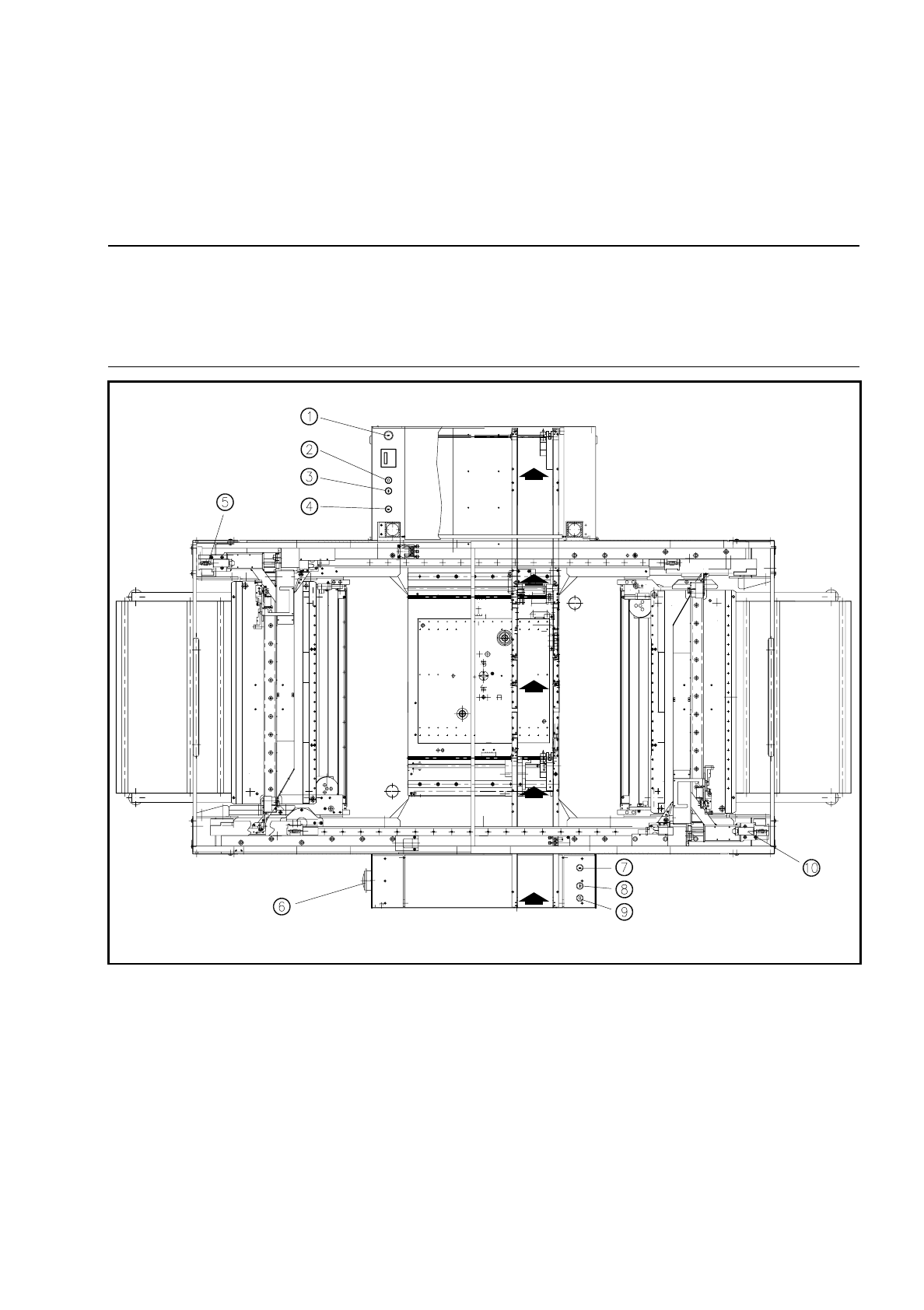
Figure 1.2.2 shows the position in the machine of main switch, cover switches, start and stop buttons,
EMERGENCY STOP button and key-operated switches:
WARNING
OO
The key-operated switch may only be unlocked for servicing or maintenance work by correspondingly quali-
fied personnel. The key should otherwise be kept secure against unauthorized access as tampering by
unqualified persons could result in death, serious injury or considerable damage to the machine.
Fig. 1.2.2 Position of the switches in the machine
- Key to Fig. 1.2.2
➀
Key-operated switch
➁
Stop button
➂
Start button
➃
Emergency stop button
➄
Cover switch
➅
Main switch
➆
Emergency stop button
➇
Start button
➈
Stop button
➉
Cover switch

1 Operational Safety SIPLACE 80 S/F/G Service Manual
Edition 04/97
1 - 10
1.2.2.1 Description of Functions
●
EMERGENCY STOP button
When the EMERGENCY STOP button is pressed the control voltage of the gantry axes will be switched out.
This means that the gantry axes are de-energized and thus no longer constitute a potential danger.
NOTE
Placement is interrupted and can, once the system is ready to work again, be resumed or aborted.
●
Key-operated switch
If the key-operated switch is locked and the covers opened the gantry axes will come to an immediate stop.
The star can be advanced but at lower speed.
WARNING
OO
Despite all of the safety features provided by the manufacturer, improper or uninformed operation of the
machine could result in serious physical injury (from the gantry, for example) and / or considerable damage to
the machine.
Safe operation of the machine requires that it is operated and maintained properly by qualified personnel in
compliance with all warning instructions.
Certain actions concerning the machine (such as servicing work, for example) call for additional training.