80S-15贴片机.pdf - 第223页
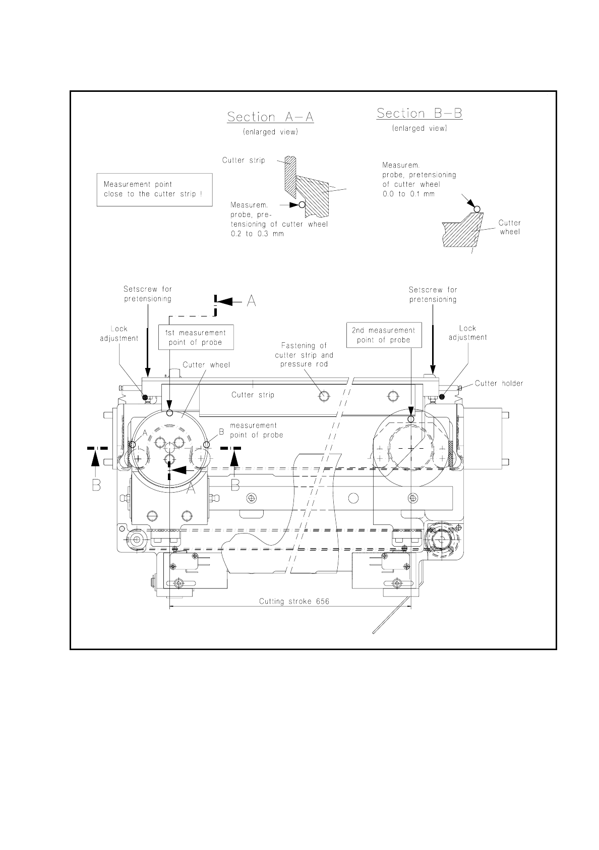
SIPLACE 80 S/ F/G Service M anual 7 Components Table Edition 04/97 7 - 41 Fig. 7. 6.2 Checking and replacing the cutter strip and c utter wheel; adjusting the pretensioning

7 Components Table SIPLACE 80 S/F/G Service Manual
Edition 04/97
7 - 40
Please note:
The measurement point must be adjacent to the cutter strip, the display must now show "0.0 mm".
●
Unscrew the thrust piece (lefthand) out of the cutter holder until the cutter wheel is pretensioned 0.2 to
0.3 mm by the cutter strip.
●
Move the cutter wheel carriage by hand into the righthand end position.
●
Move the magnetic holder on the guide rail to the right.
●
Place the measuring probe on the cutter wheel (see Fig. 7.6.2) and set it to "0".
●
Screw out the righthand thrust piece until the cutter wheel is pretensioned 0.2 to 0.3 mm.
●
Check the setting by repeating the first measurement (=lefthand). If necessary, correct again the preten-
sioning of the cutter wheel and lock both thrust pieces in this position.
●
Carry out a cutting test by
(caution! danger of physical injury from the blade!)
a large enough piece of
foil of a suitable thickness (approx. 0.2 mm) to the cutter strip and moving the cutter wheel slide by hand.
After just one cutting stroke the foil must have been cut and separated.
SIPLACE 80 S/F/G Service Manual 7 Components Table
Edition 04/97
7 - 41
Fig. 7.6.2 Checking and replacing the cutter strip and cutter wheel; adjusting the pretensioning

7 Components Table SIPLACE 80 S/F/G Service Manual
Edition 04/97
7 - 42
7.6.9 D.C. Motor
7.6.9.1 Overview to Assist Further Fault Location:
Once the faults described above have been ruled out and the motor still will not activate, there may be
–
a defect in the d.c. motors,
–
a break in the components table interface cable Y559-W1 (plug X37
→
communications unit),
–
an interruption on the "Flap opener control" board or
–
an interruption on the processor board of the communications unit.
●
Since very little effort is required to install a replacement motor, by doing so you can quickly locate the fault
more precisely.
●
Accordingly, if the new motor will not activate, first exclude a break in the "Components table interface"
cable Y559-W1.
●
Next, and for test purposes, swap over the components changeover tables. In this way you can determine
whether the fault is ultimately caused by the communications unit (including cable Y559-W1) or the "Flap
opener control" board.
●
Proceed in detail as described below.
7.6.9.2 Replacement of the Motor Unit
●
The components changeover table has already been removed from the machine in the course of fault
location.
●
To be able to access the nut of the guide pulley on cutting unit undo the screws securing the swivel cylin-
der.
●
Undo the nut securing the guide pulley of the endless toothed belt.
●
Remove the endless toothed belt.
●
Disconnect all electric cables from the motor unit.
●
Undo the four screws at the motor unit.
●
Remove the motor unit.
●
Install new motor unit and secure it using screws.
●
Connect the electric cables to the motor unit.
●
Place the cut toothed belt around the guide pulley and the motor unit.
●
Attach the clamping connector so that the ends of the cut toothed belt are joined and clamped centrally.
●
Move the cutter wheel to the park position.
●
Tension the belt by displacing the guide pulley in the elongated hole.
●
Measure the belt tension in the center of the endless toothed belt (Setpoint value: 30 - max. 35Hz).
NOTE:
Repeat the two aforementioned procedures until the belt is tensioned correctly.
●
Fasten the swivel cylinder.
●
Screw the motor onto the support (4 fillister head screws M3x5).