80S-15贴片机.pdf - 第225页
SIPLACE 80 S/ F/G Service M anual 7 Components Table Edition 04/97 7 - 43 ● Plug the push-on recepta cles incl uding capacit or onto the motor connec tions, mak ing sur e the pol arity i s corr ect ( see F ig. 7 .6.3 ). …

7 Components Table SIPLACE 80 S/F/G Service Manual
Edition 04/97
7 - 42
7.6.9 D.C. Motor
7.6.9.1 Overview to Assist Further Fault Location:
Once the faults described above have been ruled out and the motor still will not activate, there may be
–
a defect in the d.c. motors,
–
a break in the components table interface cable Y559-W1 (plug X37
→
communications unit),
–
an interruption on the "Flap opener control" board or
–
an interruption on the processor board of the communications unit.
●
Since very little effort is required to install a replacement motor, by doing so you can quickly locate the fault
more precisely.
●
Accordingly, if the new motor will not activate, first exclude a break in the "Components table interface"
cable Y559-W1.
●
Next, and for test purposes, swap over the components changeover tables. In this way you can determine
whether the fault is ultimately caused by the communications unit (including cable Y559-W1) or the "Flap
opener control" board.
●
Proceed in detail as described below.
7.6.9.2 Replacement of the Motor Unit
●
The components changeover table has already been removed from the machine in the course of fault
location.
●
To be able to access the nut of the guide pulley on cutting unit undo the screws securing the swivel cylin-
der.
●
Undo the nut securing the guide pulley of the endless toothed belt.
●
Remove the endless toothed belt.
●
Disconnect all electric cables from the motor unit.
●
Undo the four screws at the motor unit.
●
Remove the motor unit.
●
Install new motor unit and secure it using screws.
●
Connect the electric cables to the motor unit.
●
Place the cut toothed belt around the guide pulley and the motor unit.
●
Attach the clamping connector so that the ends of the cut toothed belt are joined and clamped centrally.
●
Move the cutter wheel to the park position.
●
Tension the belt by displacing the guide pulley in the elongated hole.
●
Measure the belt tension in the center of the endless toothed belt (Setpoint value: 30 - max. 35Hz).
NOTE:
Repeat the two aforementioned procedures until the belt is tensioned correctly.
●
Fasten the swivel cylinder.
●
Screw the motor onto the support (4 fillister head screws M3x5).
SIPLACE 80 S/F/G Service Manual 7 Components Table
Edition 04/97
7 - 43
●
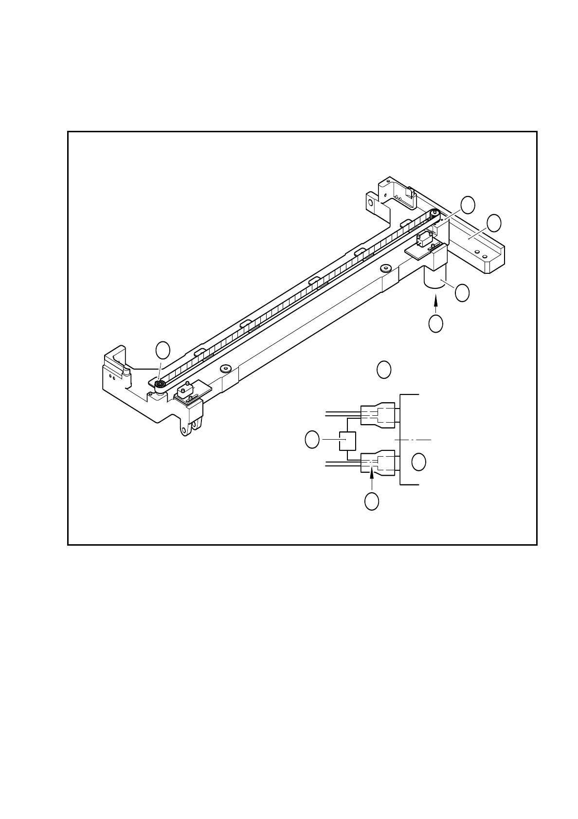
Plug the push-on receptacles including capacitor onto the motor connections, making sure the polarity is
correct (see Fig. 7.6.3).
Fig. 7.6.3 Replacing the motor or capacitor
Key to Fig. 7.6.3
1 Machine base
2 D.C. gear motor
3 Fixing screws for the gear motor, 4 M3x5 fillister head screws
4 Deflection pulley of the cut toothed belt
5 Connection cable Y637-W2
6 Ceramic capacitor 10nF / 100V
+ pole: cable colors white, brown, green
- pole: cable colors yellow, grey, pink
A Electrical connection of the gear motor
A
4
3
1
2
A
6
2
5

7 Components Table SIPLACE 80 S/F/G Service Manual
Edition 04/97
7 - 44
7.6.9.3 Checking the Functioning of the New Motor
DANGER
OOO
When the SITEST program is used for the following work with the components changeover table moved out
(connected) there is an increased danger of accidents, particularly at the tape cutting unit, due to the cutter
wheel and cutter strip. Please observe the detailed DANGER note in section 7.6.2 on page 7 - 34!
●
Connect the components changeover table which has been moved out to the power supply (mains plug,
interface connector X37).
●
Connect the multimeter to the motor of the tape cutting unit, making sure the measuring cables are long
enough.
●
Position the multimeter so that you can read it easily during the activation which follows.
●
Switch on the machine and load the SITEST program.
●
Have a cutting stroke made. Select: "BE table"
→
"Single function"
→
"Tape cutter".
●
During the stroke, read the multimeter: If the cutter wheel pretensioning and the toothed belt tension are
correct you will read 2 - 2.5 A which is desired the power consumption.
●
The cutter wheel carriage must actuate the righthand limit switch and move back to the parking position.
–
If the motor now is activated, carry out the "Concluding work" (see section 7.6.15 "Concluding Work").
–
If the motor still does not activate, proceed, as described below.
–
The cutter wheel carriage must not hit against the buffer (replace clamping connector, if necessary).
7.6.9.4 Checking the Cable Y559-W1 for Breaks
●
Quit the SITEST program and switch the machine off at the main switch.
GEFAHR
QQQ
Switch off the machine at the main switch and disconnect it from the power supply.
●
To check the cable for breaks proceed now as described in section 7.5 "Communications Unit".
–
In the event of a fault replace the cable Y559-W1 as described in section 7.5 "Communications Unit".
–
If, however, there is nothing wrong with the cable Y559-W1, continue fault location as follows.
7.6.9.5 Determining whether the Communications Unit or the Flap Opener Control-
ler is Defective
The + 30 VDC voltage and the signal for the tape cutter are routed as follows:
processor board, plug X5
→
"Flap opener control" board (IC)
→
processor board, plug X4 (see circuit dia-
grams folder, circuit diagrams 1710460- Y0031-...-L-..., Sh. 3 and -Y0014-...-L-.., Sh. 1).
–
You can quickly narrow down the location of the break by connection to an intact communications unit
(replacement of the components changeover tables). The procedure in detail is as follows:
●
Quit the SITEST program and switch the machine off at the main switch.