80S-15贴片机.pdf - 第231页
SIPLACE 80 S/ F/G Service M anual 7 Components Table Edition 04/97 7 - 49 7.6.12 Swivel Mechanism – If the pre ssure rod is not p ressed strongl y enough a gainst th e sprin g bows or the emp ty tape du ring the cutting …
7 Components Table SIPLACE 80 S/F/G Service Manual
Edition 04/97
7 - 48
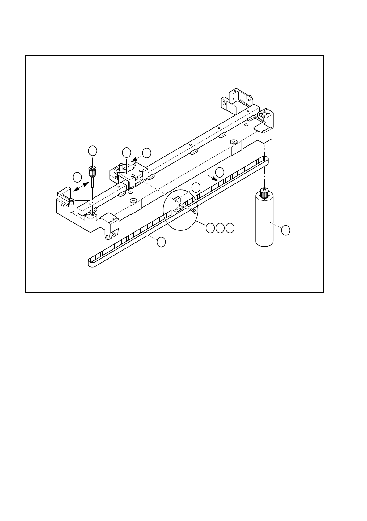
Fig. 7.6.5 Replacing and tensioning the endless toothed belt
1 Clamping connector
2 Drive motor
3 Cutter wheel carriage
4 Deflection pulley
5 Endless toothed belt
A Insert the endless toothed belt
B Check whether the toothing of the clamping connector has engaged with the toothing of the endless
toothed belt.
C Screw in the clamping connector without pinching the toothed belt.
D Measure the belt tension in the middle of the toothed belt, setpoint value 30-35 Hz.
E To measure the belt tension move the cutter wheel carriage to its left end position.
F Correct the belt tension, if necessary, by moving the deflection pulley.
,,
4
F
E
3
5
2
1
D
A B C

SIPLACE 80 S/F/G Service Manual 7 Components Table
Edition 04/97
7 - 49
7.6.12 Swivel Mechanism
–
If the pressure rod is not pressed strongly enough against the spring bows or the empty tape during the
cutting process (see Fig. 7.6.8), the tapes may slip over one another during cutting (tape jam, poor cuts).
–
If the pressure rod does not swing out far enough when the tape cycles on, the tapes may not slide down
the empty tape channel which will also lead to a tape jam.
A fault in the swivel movement can indicate a fault in the 5.6 bar compressed air branch, in the solenoid valve,
in the compressed air cylinder, or incorrect adjustment of the restrictor valves or fatigued tension springs.
–
Detailed information on the electrical and pneumatic systems and on the functional sequence will be found
under "Overview" in section 7.1.4 "Empty Tape Cutting Device".
7.6.12.1 Checking the Swivel Movement
●
Please observe the DANGER notes in section 7.6.2 on page 7 - 34, concerning working with the SITEST
program
(danger of physical injury!)
.
●
Select "Abort placement" and load the SITEST program.
●
If necessary, have on hand the detailed functional sequence described in section 7.1.4 "Empty Tape Cut-
ting Device".
●
Select "BE table"
→
"Single function"
→
"Tape cutter".
●
At the same time check by eye the empty tapes and the swivel movement of the pressure rod.
–
If the pressure rod does not swing far enough in or out, check the compressed air branch as described
below.
–
If the pressure rod swings in too slowly or bounces as it swings in or out, adjust the supply or exhaust
air restrictor valve (see "Concluding work").
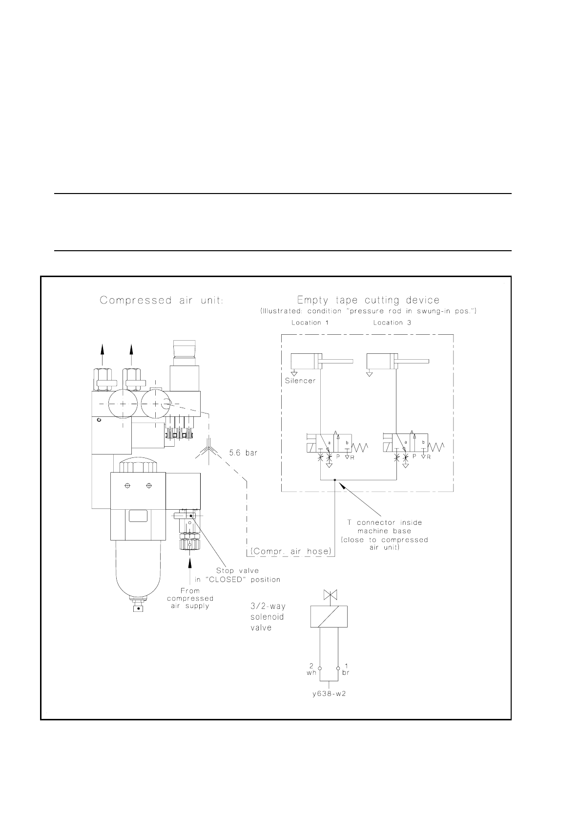
7.6.12.2 Checking the Compressed Air Branch
●
Remove the compressed air unit cover from the machine base (undo 2 special socket-head cap screws
M3).
●
Check the threaded hose connections at the solenoid valve of the tape cutting unit (see Fig. 7.6.7) and at
the compressed air unit (see Fig. 7.6.6) for leaks.
●
If these screwed connections are okay, proceed as follows:
DANGER
QQQ
Switch the machine off at the main switch and disconnect it from the power supply.
NOTE
OOO
Switch the compressed air supply line at the shut-off valve of the compressed air unit (see Fig. 7.6.6).
●
Check the compressed air hose between the compressed air unit and the solenoid valve:
–
If the compressed air hose pinched, replace it. Replace all of the cable lacings.
7 Components Table SIPLACE 80 S/F/G Service Manual
Edition 04/97
7 - 50
●
Open the shut-off valve in the compressed air supply line and switch the machine on at the main
switch.
●
Check the figures shown by the pressure gauges and refit the cover over the compressed air unit
at the machine base (2 special socket-head cap screws M3).
–
If there is still no fault, the compressed air cylinder or the solenoid valve could be defective. Continue
work with the next section.
NOTE:
The + 30 VDC electric circuit and the activation of the solenoid valve were already checked earlier in sec-
tion 7.6.2.1.
Fig. 7.6.6 Compressed air connection of the tape cutting units and electrical connection of the solenoid valve (cable Y637-W1/W2)