80S-15贴片机.pdf - 第236页
7 Components Table S IPLACE 80 S/F/G Servic e Manual Edition 04/97 7 - 54 7.6.14 Fitting and Aligning the Empty Tap e Cutting Unit and Empty Tape Channel With this work i t is assum ed that t he flap opener i ncludin g s…
SIPLACE 80 S/F/G Service Manual 7 Components Table
Edition 04/97
7 - 53
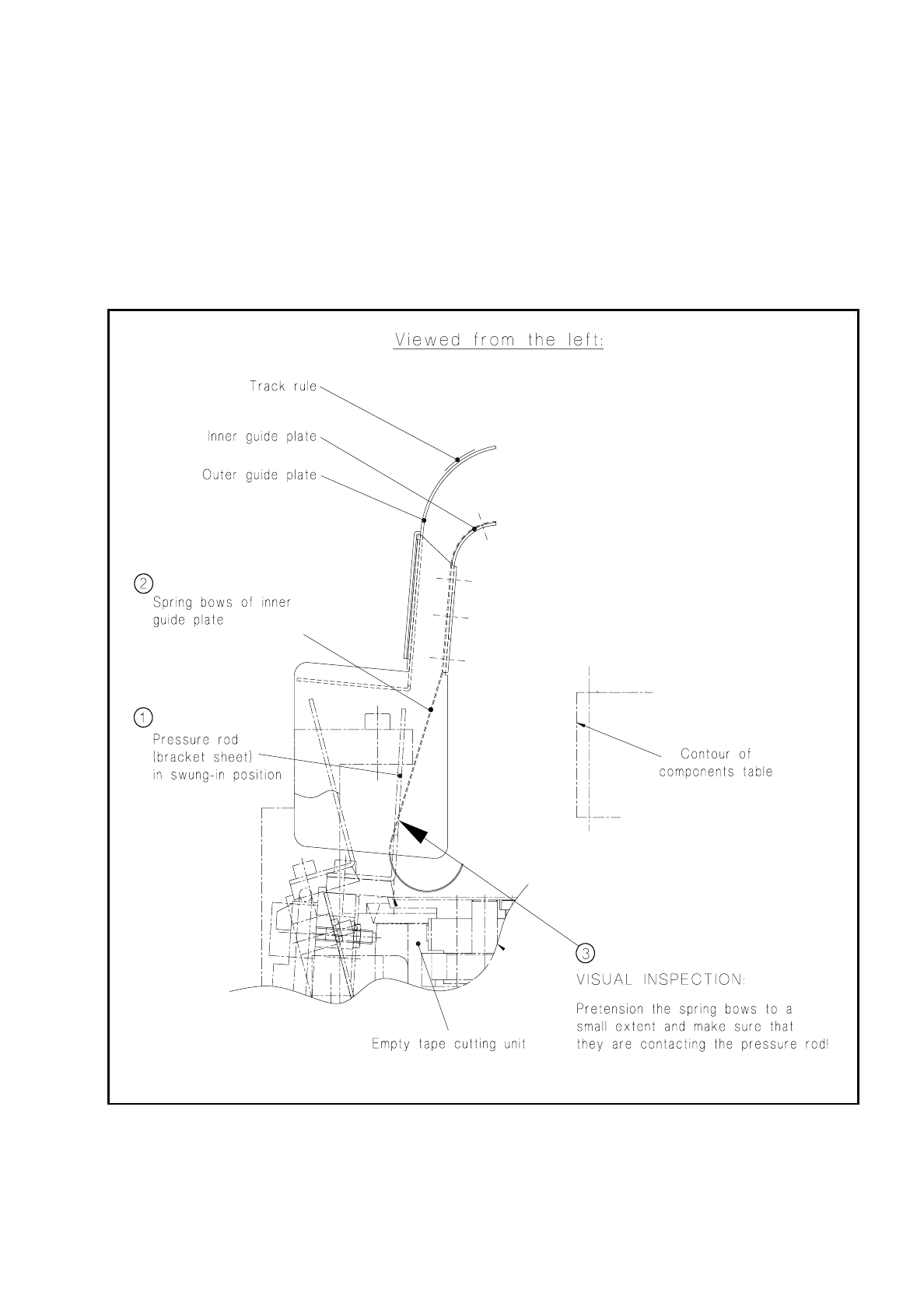
7.6.13 Empty Tape Channel: Checking and Replacing the Spring Bows
If individual tapes are not being cut (tape jam in individual feeder modules), this may be due to the "guide
plate, inner" having bent spring bows.
●
To check the spring bows proceed as shown in Fig. 7.6.8.
●
If individual spring bows are bent, install a new "empty tape channel complete".
●
Adjust the new empty tape channel so that it is positioned symmetrically to the pressure rod (see below).
Fig. 7.6.8 Aligning the empty tape channel to the pressure rod when refitting
7 Components Table SIPLACE 80 S/F/G Service Manual
Edition 04/97
7 - 54
7.6.14 Fitting and Aligning the Empty Tape Cutting Unit and Empty
Tape Channel
With this work it is assumed that the flap opener including strip has already been correctly aligned after rein-
stallation (see section 7.4 "Flap Opener (Magazine Openers)").
In the following cases align the empty tape channel symmetrically to the pressure rod:
–
In the event of a fault, as when the outer tapes in each case (tracks 1/120) are not being cut correctly.
–
When refitting the empty tape cutting unit, the flap opener and/or the empty tape channel.
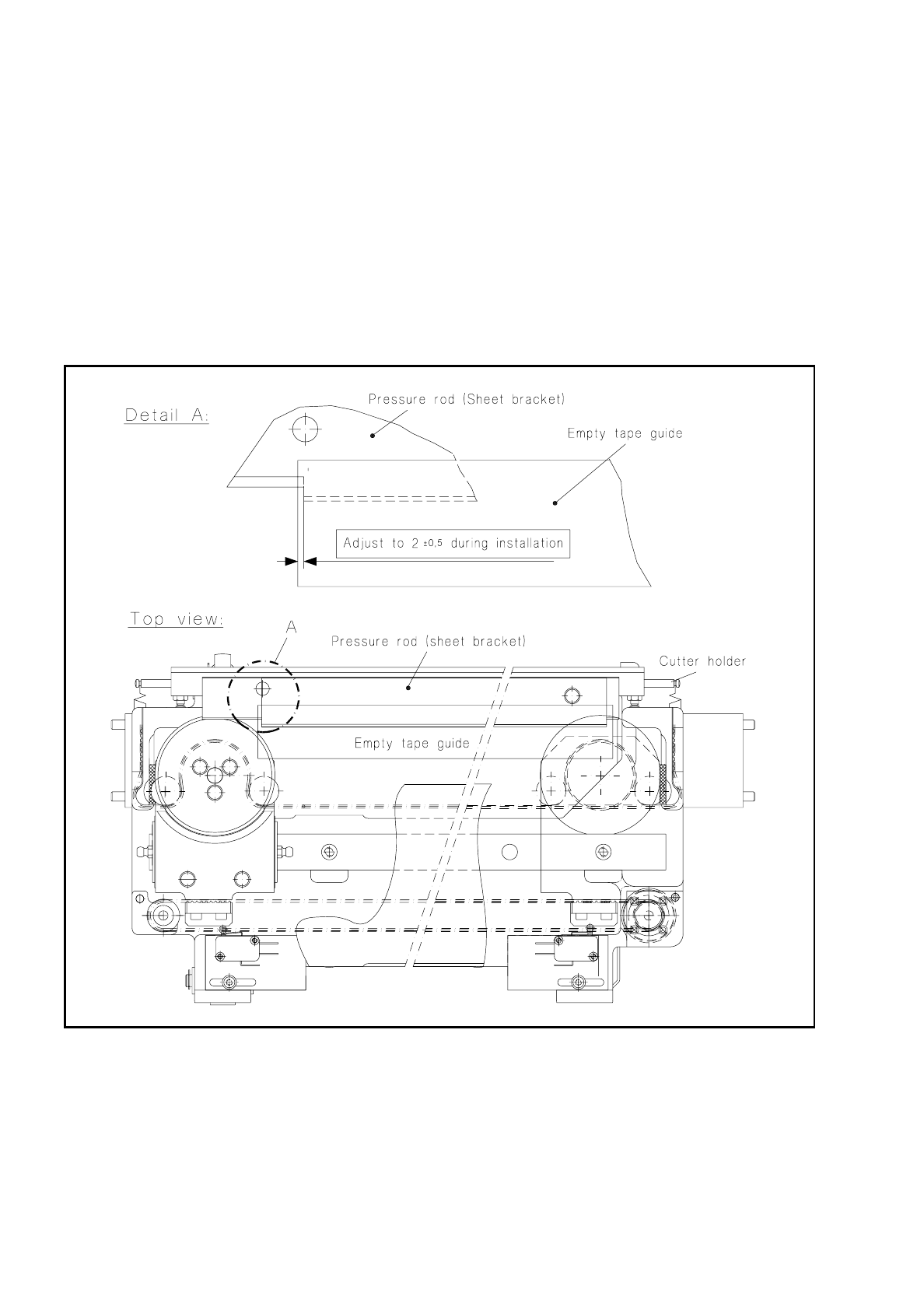
Fig. 7.6.9 Aligning the empty tape channel to the pressure rod when refitting
●
Reinstalling and adjusting the empty tape channel:
If it is only the empty tape channel which has been replaced, proceed as follows.
●
If necessary, unscrew the mounting of the empty tape channel to the flap opener (2 socket-head cap
screws M4, see Fig. 7.1.3 in section 7.1 "Overview") and align the empty tape channel symmetrically
to the pressure rod of the cutting unit as shown in Fig. 7.6.9.
●
Screw down the guide channel in this position on the flap opener (2 socket-head cap screws M4).

SIPLACE 80 S/F/G Service Manual 7 Components Table
Edition 04/97
7 - 55
●
Reinstalling and adjusting the empty tape cutting unit:
●
Place the empty tape cutting unit on the supporting brackets on the left and right of the machine base,
and tighten up the screws at the slots in the supporting brackets only to the point that you can still slide
the cutting unit to position it correctly.
●
Now fit the empty tape channel to the flap opener (2 socket-head cap screws M4).
●
Align the empty tape cutting unit in the supporting bracket slots (at the machine base) so that the
angle strip on both the x and y axes is positioned symmetrically to the empty tape channel.
●
To check this, pull the "guide plate, outer" upwards and out (see Fig. 7.6.9) and check by looking
down into the empty tape channel: the pressure rod - and thus the tape cutting unit - must run parallel
to the empty tape channel and on the left and right be set back 2 mm from the outer edge of the empty
tape channel.
7.6.15 Concluding Work
●
The machine is switched off at the main switch.
●
Move the cutter wheel carriage by hand
(CAUTION: danger of physical injury at the cutter strip!)
into
the parking position on the left.
●
Using the lift truck replace the components changeover table back in the centering facility in the machine
base and close the two clamping clips at the components table.
●
Connect up compressed air hoses (tape cutter and, if applicable, the flap opener). Lay the flap opener
hose between machine base and tensioning element (= guard in front of the cutter wheel).
●
Connect the components changeover table back up at the machine base: plug X37, mains plug and, if
applicable, compressed air connection (when the option "components table air supply" is installed).
●
After reinstallation of the empty tape cutting unit, make sure that the plug connections at the flap opener
board (X38) and at the tape cutting unit (X3ak) are plugged back in (see Fig. 7.1.3).
●
Slide the side cover at the component loading point back in place and close the protective covers.
●
If applicable, switch the compressed air supply back on at the shut-off valve of the compressed air unit
(see Fig. 7.6.6).
●
If applicable, fit the cover over the compressed air unit at the machine base.
●
Switch the machine on and load the SITEST program.
●
Make sure that the empty tape cutting unit functions correctly by making individual cutting strokes or by
cont. operation: Select "BE table"
→
single function / continuous loop CL
→
"Tape cutter".
●
Check at the same time the swivelling movement of the pressure rod:
–
Swinging out too slowly or bouncing = Adjust the inlet air restrictor valve at the solenoid valve (Fig.
7.6.6 and Fig. 7.6.7), Swinging in too slowly or bouncing = Adjust the exhaust air restrictor at the sole-
noid valve.
Please note:
Since the cutting stroke begins at the same time as the swinging-in move-
ment (the solenoid valve and motor are connected in parallel (see Fig. 7.6.6), the swinging-in
movement must take place as fast as possible, but without bouncing. If this is not the case, it will result
in faults in the tape-cutting.
●
Load the station software and start the placement sequence.