80S-15贴片机.pdf - 第242页
7 Components Table S IPLACE 80 S/F/G Servic e Manual Edition 04/97 7 - 60 ● If nece ssary, check the compr essed air h ose whic h runs in the interior of th e mach ine ba se. If the compres sed a ir hose is pinc hed, rep…

SIPLACE 80 S/F/G Service Manual 7 Components Table
Edition 04/97
7 - 59
–
If the "A1" LED is not illuminated, this may indicate an interruption in the communications unit.
Proceed as described in the section 7.5 "Communications Unit".
–
If the "A1" LED of the location tester is on, this means the control signal is reaching the socket.
A fault in the compressed air feed module can be excluded by connecting it to the external power
supply (see section above), which will mean that there must be a fault in the 5 bar compressed air
branch. Continue work with the following section.
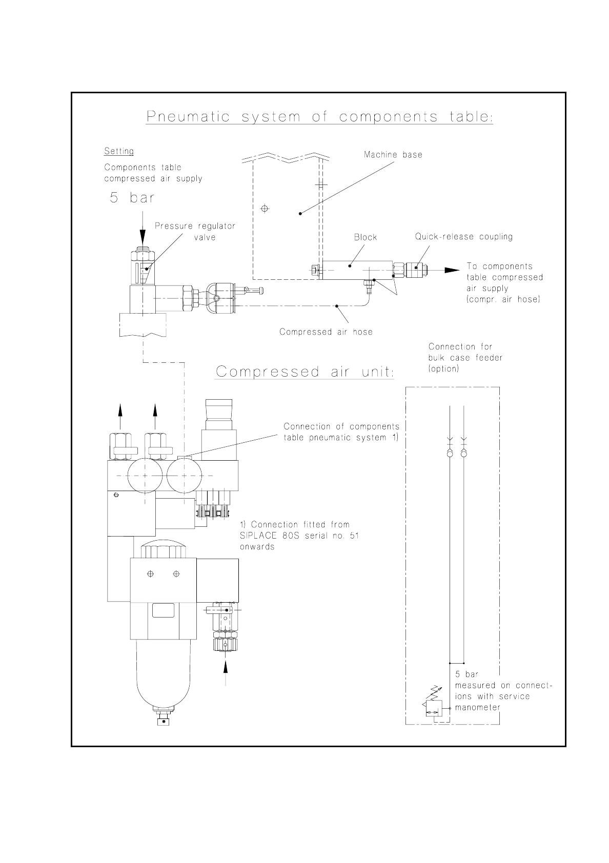
7.7.3 Fault Location and Corr.: Compr. Air Unit and Comp. Table
Pneum. System
●
If you have already determined that the fault is not in the module or in the communications unit (see pre-
ceding section), select "Abort placement" in order that all of the components are returned which were
picked up at the placement heads during the course of the ensuing reference run. The placement heads
move into the waiting position above the corresponding components loading point.
●
Remove the cover over the compressed air unit from the machine base (undo 2 special socket-head cap
screws using a size 3 socket spanner).
●
Check the 5.6 bar operating pressure (see User’s Manual, Section 9).
●
Check all of the screwed hose connections of the 5 bar compressed air branch which supplies the feed
module:
●
At the pressure regulating valve of the compressed air unit (see Fig. 7.7.1),
●
at the block, components table pneumatic system, on the right of the machine base (see Fig. 7.7.1)
and
●
at the components table compressed air supply (see Fig. 7.1.5 in the section 7.1 "Overview").
●
If the air is leaking at the block, switch off the machine and replaced the damaged sealing rung (see Fig.
7.7.1).
●
If there are no leaks at any point up to the connection to the components table compressed air supply,
switch off the machine at the main switch and then undo the threaded hose connection at the pressure
regulating valve of the compressed air unit (for components table pneumatic system connections, see Fig.
7.7.1).
●
Connect the service manometer by the threaded hose connection directly to the pressure regulating valve.
●
Switch on the machine at the main switch (the control system remains off). Compressed air is on.
●
The service manometer must show 5 bar precisely; if it does not, set the correct pressure using the adjust-
ment screw (screwdriver for socket-head screws):
–
If you cannot get the required 5 bar pressure, replace the pressure regulating valve (after disconnect-
ing the machine from the power supply and compressed air network!).
–
If the compressed air was at the correct pressure, check the pressure at the block of the components
table pneumatic system (service manometer). If you measure a different value here, switch off the
machine at the main switch and disconnect the machine from the power supply!
DANGER
QQQ
Switch the machine off at the main switch and disconnect it from the power supply.

7 Components Table SIPLACE 80 S/F/G Service Manual
Edition 04/97
7 - 60
●
If necessary, check the compressed air hose which runs in the interior of the machine base. If the
compressed air hose is pinched, replace it. Fit the cable lacings back in place, reconnect the
compressed air hose to the block and to the components table compressed air supply.
●
Connect the machine to the mains and switch on.
●
Fit the cover to the machine base (size 3 screwdriver for socket-head screws).
●
If you still have not been able to determine what the fault it, check the components table compressed air
supply unit.
SIPLACE 80 S/F/G Service Manual 7 Components Table
Edition 04/97
7 - 61
Fig. 7.7.1 Testing the compressed air branch of the "Compressed air unit - components table pneumatic system"