80S-15贴片机.pdf - 第245页
SIPLACE 80 S/ F/G Service M anual 7 Components Table Edition 04/97 7 - 63 ● Lift out th e transp arent side cover (at the compo nents loa ding po int) and open th e slidin g door as wide as poss ible . ● Make a n ote of …
7 Components Table SIPLACE 80 S/F/G Service Manual
Edition 04/97
7 - 62
7.7.3.1 Fault Location and Correction: Components Table Compressed Air Supply
●
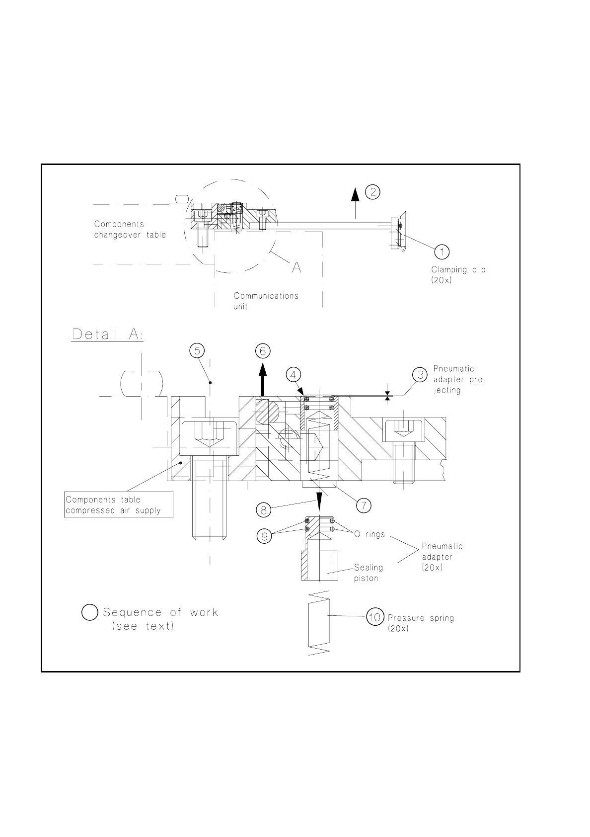
Check the clamping clip of (see Fig. 7.7.2, Item 1) of the module which is not conveying properly. It must
be correctly closed and press the module correctly against the support strip. If necessary, replace the
clamping clip (undo 2 countersunk screws M3).
Fig. 7.7.2 Components table compressed air supply: checking and replacing o-rings and pressure springs of the pneumatic adapters
●
If this does not correct the fault, switch off the machine at the main switch and slide the corresponding
placement head by hand into the area within the PCB conveyor to prevent the head being damaged when
the modules are subsequently removed.
Note: You must observe a minimum clearance here of the x gantry axes - the axis must not be at the crash
switch (see User’s Manual, Section 9, subsection "Empty tape cutting device".

SIPLACE 80 S/F/G Service Manual 7 Components Table
Edition 04/97
7 - 63
●
Lift out the transparent side cover (at the components loading point) and open the sliding door as wide as
possible.
●
Make a note of which feed modules are assigned to which track. The assignment of the modules is speci-
fied in the set-up optimization and must be restored when the modules are fitted back (see detailed infor-
mation in the User’s Manual, Section "Maintenance", under "Components tables").
NOTE
Make sure that no components are allowed to drop into the working area of the machine while the modules
are being removed or this will result in additional malfunctions.
●
Make a note of the module track assignments (see NOTE in the User’s Manual, Section 9, "Components
tables) and remove any feed module which is not feeding components properly (see Fig. 7.7.2, Item 2):
●
To do so, pull out the plug connections at the connections panel of the communications unit, open the
corresponding clamping clips at the compressed air feed modules and lift them upwards and out
●
Check that the adapter is sticking out (Item 3). If the end face of the adapter is down inside the hole,
replace the adapter pressure spring.
●
Check whether air is leaking at the edge of the adapter (see Item 4). In this case replace the o-ring of the
adapter. Mark the faulty tracks with a transparency marker pen, preferably at the corresponding clamping
clip to enable you to find the track again quickly later.
●
To replace the pressure spring or the adapter itself, proceed as follows:
●
After making a note of the module track assignments, remove all remaining compressed air feed mod-
ules in the way described above.
●
Unscrew the hose connection at the components table compressed air supply (see Fig. 7.1.5) and pull
off the compressed air hose.
●
Unscrew the mounting of the components table compressed air supply to the components table
(3 socket-head cap screws M8, see Item 5).
●
Lift the complete unit vertically away until the 3 locating pins are exposed (see Item 6).
●
Set the complete unit carefully down on its head (the module location area faces downwards) and
unscrew and remove the retainer strip on the underside of the components table compressed air sup-
ply (undo 7 countersunk screws M3, see Item 7).
●
Pull the leaky adapter out of the hole (see Item 8). Replace both o-rings (see Item 9). For the Item No.
please refer to "Spare parts". If necessary, at this time clean the sides of the adapter.
●
Remove the fatigued pressure spring out of the adapter hole (see Item 10) and insert a new spring.
●
Carefully insert the adapter with the o-rings into the hole while rotating it a little. Make sure that all of
the pressure springs have been replaced.
●
Fit the retainer strip over the adapters (7 countersunk screws M3).
●
Make sure that the area of the components table on which the components table compressed air sup-
ply will be positioned is clean.
●
Pick up the components table compressed air supply with both hands and with the locating pins point-
ing downwards insert it into the centering holes in the components table.
●
Screw the components table compressed air supply to the components table rail (3 socket-head cap
screws M8).
●
Connect the compressed air hose to the components table compressed air supply.

7 Components Table SIPLACE 80 S/F/G Service Manual
Edition 04/97
7 - 64
●
Refit the feed modules in (clean!) components table, making sure that each module is restored to its
assigned track. To do so, either refer to your notes or if necessary to the instructions for restoring track
assignments in the User’s Manual, Section 9, under "Components tables".
●
Finally, check the track assignments. Plug the feed modules into their allocated (= to be found below them)
sockets in the communications unit.
●
Slide the side cover back into place and close the top cover; switch the machine on.
●
Checking functioning: If the SITEST program is loaded. set the output for the corresponding track and / or
for the entire location (1; 3); otherwise, with the station software make a trial placement run with compo-
nents being picked up from the compressed air feed modules.
❒