80S-15贴片机.pdf - 第263页
SIPLACE 80S/F/G Service Manual 8 IC Head Edition 01/97 8 - 15 Fig. 8. 3.2 Servicing work on the IC head Key to Fi g. 8.3.2 1 Linear b all be aring 2 Clam ping piec e 3 Hexagon s ocket he ad screw 4 P recision shaft 5 x 7…

8 IC Head SIPLACE 80S/F/G Service Manual
Edition 01/97
8 - 14
●
Firmly clamp the clamping piece (item 6, Fig. 8.3.2 page 8 - 15). Ensure it does not strike against the top
or the bottom when the sleeve is moved up and down. If necessary, center the clamping piece.
●
Check again that the sleeve moves easily when the z axis clamping device is deactivated. If it does not,
the problem may be caused because the precision shaft (item 4) and the sleeve are not aligned parallel to
one another.
●
Align the two parts as follows:
–
Push the sleeve until it reaches the top position.
–
Using a 2 mm hexagon socket head spanner, loosen the screw (item 3) on the clamping piece
(item 2). The precision shaft (item 4) will align itself.
–
Tighten the hexagon socket head screw (item 3) once more. The precision shaft is now aligned.
–
Re-establish the vacuum connector.
●
Set the zero point correction values for the z axis (see section 8.3.9) and the dr axis
(see section 8.4.4, page 8 - 17).
8.3.9 Determine the Zero Point Correction for the Z Axis
PLEASE NOTE
The zero point correction is correct if the z axis is at the top mechanical stop and a value of - 10 digits for the
z position is displayed.
The zero point correction value should be between - 80 and - 120 digits. If this is not the case, you will have to
move the toothed belt slightly. The new zero point correction value can be calculated using the following
equation:
ZPC
NEW
= ACTUAL - DESIRED + ZPC
OLD
Example:
Position at the top mechanical stop = -15 (ACTUAL)
Desired value = -10 DESIRED)
ZPC
OLD
= - 110 digits
ZPC
NEW
= - 15 - (-10) + (- 110)
= - 15 + 10 - 110
= - 115
SIPLACE 80S/F/G Service Manual 8 IC Head
Edition 01/97
8 - 15
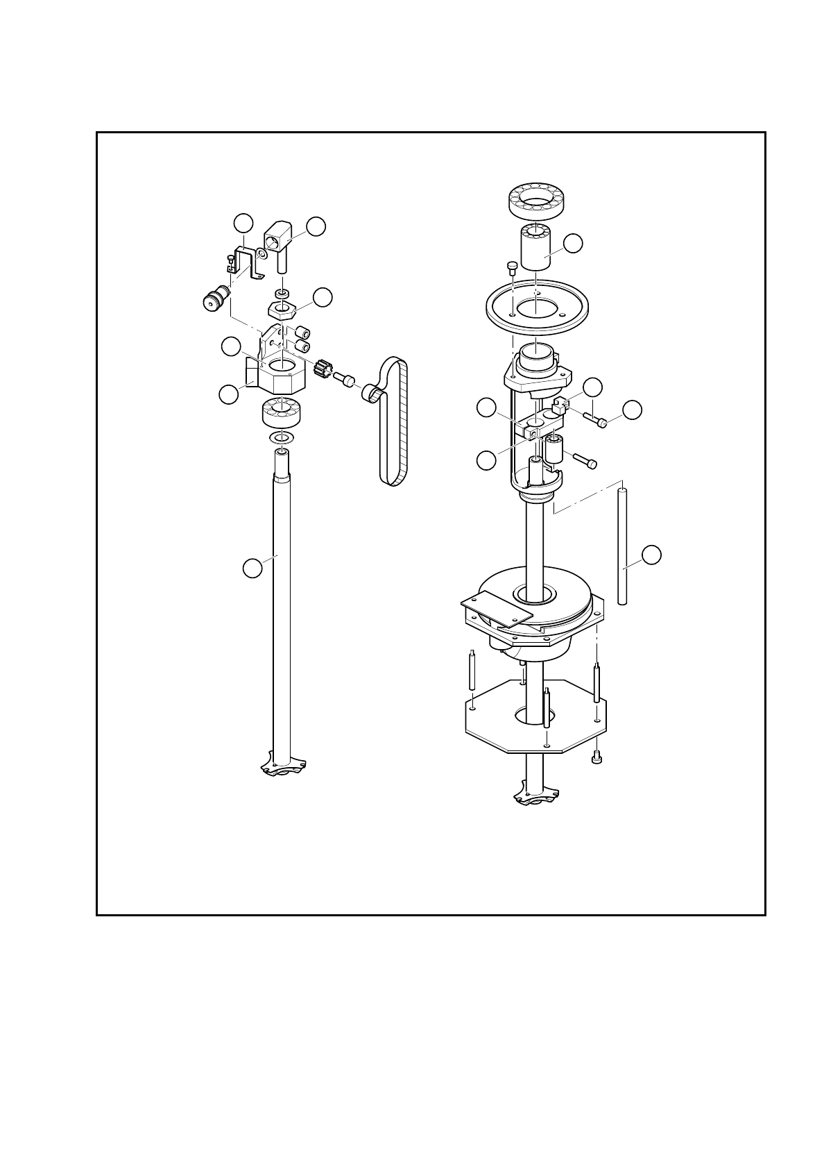
Fig. 8.3.2 Servicing work on the IC head
Key to Fig. 8.3.2
1 Linear ball bearing 2 Clamping piece
3 Hexagon socket head screw 4 Precision shaft 5 x 76.5
5 Hexagon socket head screw (2 mm) 6 Clamping piece
7 Clip 8 Vacuum connector
9 Hexagon nut 10 Anti-rotation lock
11 Bearing housing 12 IC head sleeve
5
4
3
2
1
6
9
8
7
10
11
12

8 IC Head SIPLACE 80S/F/G Service Manual
Edition 01/97
8 - 16
8.4 Servicing Work on the Dr Axis
8.4.1 Tools, Equipment and Consumables
8.4.2 Spare Parts
8.4.3 Replace Motor with Tacho for the Dr Axis
See item 4 in Fig. 8.3.1 page 8 - 12
To disassemble the motor
–
Detach all electrical cables to and from the motor.
–
Loosen the two M3 hexagon socket head screws fixing the motor in place.
–
Remove the motor from the top.
To reassemble the motor
–
Clean the rubber lining of the friction wheel (item 3) and the ring (Ø 12 mm) on the motor shaft with isopro-
pyl alcohol.
–
Replace the motor and fix in place.
Ensure that there is good contact between the motor drive shaft and the friction wheel.
–
Check that the axis is moving correctly with reference to the Adjusting Instructions.
From item number
Hexagon socket head screw key, set
SITEST program
Adjusting Instructions
Nozzle, type 416 00322545-01
Isopropyl alcohol
From item number
Motor/tacho (dr axis) 00306383-02