80S-15贴片机.pdf - 第269页
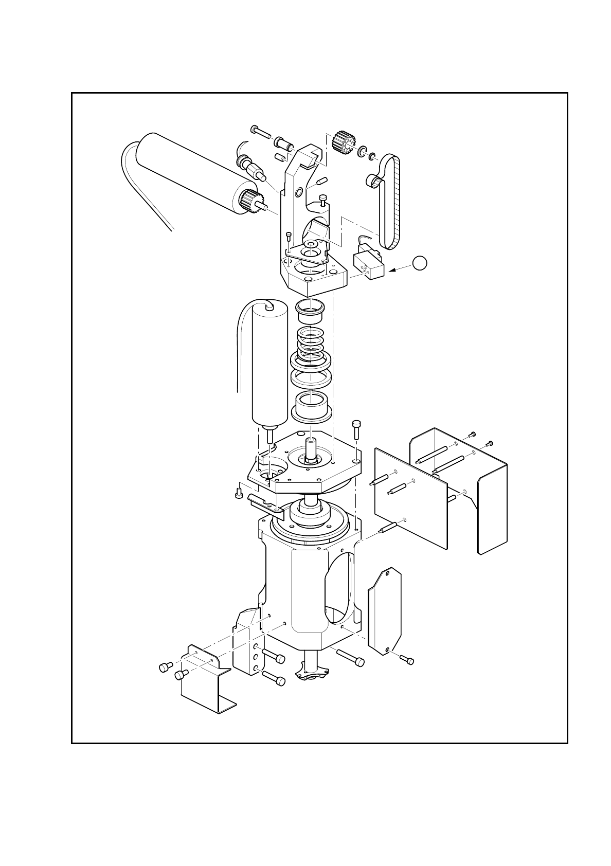
SIPLACE 80S/F/G Service Manual 8 IC Head Edition 01/97 8 - 21 Fig. 8.5.1 Solenoid valve for z axis clamping device Key to Fi g. 8.5.1 1 Solenoid valv e for z axis clampin g dev ice: Compr essed air supp ly at 2.3 bar 1
8 IC Head SIPLACE 80S/F/G Service Manual
Edition 01/97
8 - 20
8.5 Servicing Work on the Pneumatic System
8.5.1 Tools, Equipment and Consumables
8.5.2 Spare Parts
8.5.3 Replace Solenoid Valve for Z Axis Clamping Device
See item 1 in Fig. 8.5.1 page 8 - 21
●
Loosen the two slotted screws that fix the solenoid valve in place.
●
Remove the connecting cable.
●
Fix the new solenoid valve in place and reconnect to the power supply.
PLEASE NOTE
The small red push-button is used only to manually actuate the solenoid valve, i.e. to release the clamping
device.
From item number
Hexagon socket head screw key, set
SITEST program
UNISILKON L250L 00310259-01
From item number
Valve (clamping device for z axis) 00306387-02
Valve (vacuum) 00306389-03
Valve (forced air) 00306388-02
Collet bush PK-3 00303552-01
O-ring 3 x 1 FPM 80SB 00301723-01
O-ring 5 x 1.5 NBR 70B 00305480-01
Vacuum nozzle for the IC head 00318370-01
O-ring 8 x 1 NBR 70B 00201179-01
Silencer G-1/8 CV05 HS 00308498-01
Hose connector T-PK-3 00303088-01
Nipple with male threaded end CN-M3-PK-3 00305374-01
SIPLACE 80S/F/G Service Manual 8 IC Head
Edition 01/97
8 - 21
Fig. 8.5.1 Solenoid valve for z axis clamping device
Key to Fig. 8.5.1
1 Solenoid valve for z axis clamping device: Compressed air supply at 2.3 bar
1
8 IC Head SIPLACE 80S/F/G Service Manual
Edition 01/97
8 - 22
8.5.4 Replace the ’Vacuum Generator ON’ Solenoid Valve
See items 1 and 2 in Fig. 8.5.2 page 8 - 23
This valve switches the 5.2 bar compressed air supply for the vacuum generator.
To disassemble the valve
●
Loosen the two 2.5 mm hexagon socket head screws that fix the block in place (item 2, Fig. 8.5.2).
●
Loosen the two slotted screws that fix the solenoid valve in place on the block.
●
Remove the air hose and the power cable.
To reassemble the valve
●
Reverse the above sequence to assemble the valve.
PLEASE NOTE
On the underside of the valve, there is a white push-button for manually actuating the valve.
8.5.5 Replace the ’Forced Air ON’ Solenoid Valve
See item 3, Fig. 8.5.2 page 8 - 23
●
Loosen the two slotted screws that fix the valve in place.
●
Remove the air hose and the power cable.
●
Reverse the above sequence to assemble the valve.
The red push-button is used to manually actuate the valve.
8.5.6 Check the Vacuum System
See Fig. 8.5.3 page 8 - 25
A drop in the vacuum generation performance may be caused by one of the following:
–
The silencer (item 6) is dirty.
–
The vacuum nozzle (item 4) is dirty.
–
There is a leak in the pneumatic hose system.