80S-15贴片机.pdf - 第271页
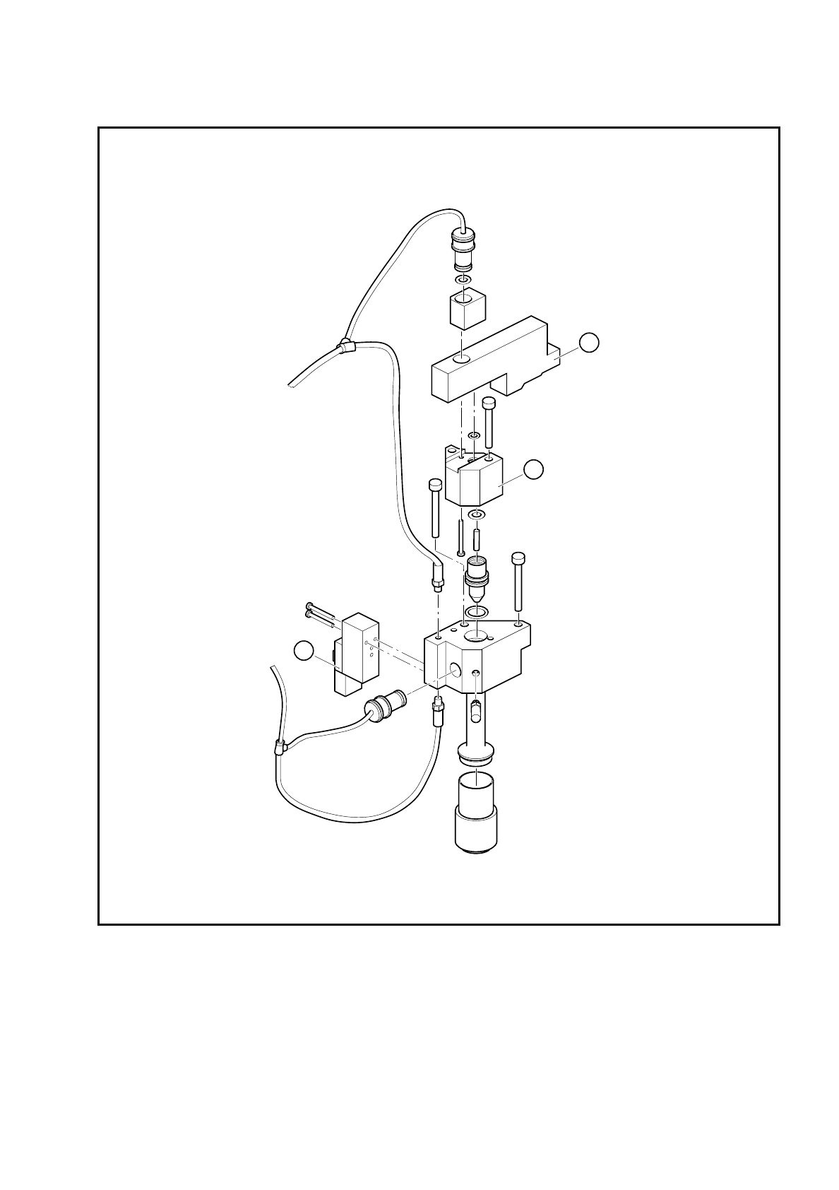
SIPLACE 80S/F/G Service Manual 8 IC Head Edition 01/97 8 - 23 Fig. 8. 5.2 ’Vacuum ON’ and ’Forced air’ solenoid valves Key to Fi g. 8.5.2 1 ’Vacuum ON' so lenoi d valve 2 Space r 3 ’Forced a ir’ so lenoi d valve 3 2…
8 IC Head SIPLACE 80S/F/G Service Manual
Edition 01/97
8 - 22
8.5.4 Replace the ’Vacuum Generator ON’ Solenoid Valve
See items 1 and 2 in Fig. 8.5.2 page 8 - 23
This valve switches the 5.2 bar compressed air supply for the vacuum generator.
To disassemble the valve
●
Loosen the two 2.5 mm hexagon socket head screws that fix the block in place (item 2, Fig. 8.5.2).
●
Loosen the two slotted screws that fix the solenoid valve in place on the block.
●
Remove the air hose and the power cable.
To reassemble the valve
●
Reverse the above sequence to assemble the valve.
PLEASE NOTE
On the underside of the valve, there is a white push-button for manually actuating the valve.
8.5.5 Replace the ’Forced Air ON’ Solenoid Valve
See item 3, Fig. 8.5.2 page 8 - 23
●
Loosen the two slotted screws that fix the valve in place.
●
Remove the air hose and the power cable.
●
Reverse the above sequence to assemble the valve.
The red push-button is used to manually actuate the valve.
8.5.6 Check the Vacuum System
See Fig. 8.5.3 page 8 - 25
A drop in the vacuum generation performance may be caused by one of the following:
–
The silencer (item 6) is dirty.
–
The vacuum nozzle (item 4) is dirty.
–
There is a leak in the pneumatic hose system.
SIPLACE 80S/F/G Service Manual 8 IC Head
Edition 01/97
8 - 23
Fig. 8.5.2 ’Vacuum ON’ and ’Forced air’ solenoid valves
Key to Fig. 8.5.2
1 ’Vacuum ON' solenoid valve
2 Spacer
3 ’Forced air’ solenoid valve
3
2
1

8 IC Head SIPLACE 80S/F/G Service Manual
Edition 01/97
8 - 24
8.5.6.1 Replace the Silencer
●
Check the silencer at regular intervals for contamination, following the instructions given in the Mainte-
nance section of the User Manual. To do this, unscrew the silencer and replace if necessary.
8.5.6.2 Clean or Replace the Vacuum Nozzle
To disassemble the vacuum nozzle
●
Loosen the two 2.5 mm hexagon socket head screws that fix the spacer in place (item A, Fig. 8.5.3).
●
Lift out the spacer and pull the vacuum nozzle out of its hole.
●
Check the vacuum nozzle (item 4, Fig. 8.5.3) for dirt and clean if necessary.
●
Check the tip of the vacuum nozzle for damage and replace if necessary.
●
Check the O-rings in the spacer (item 2) and on the vacuum nozzle (items 3 and 5) for damage. Replace
the O-rings if necessary. Lightly grease the new or cleaned O-rings with UNISILKON L 250L.
To reassemble the vacuum nozzle
Reverse the above sequence to reassemble.
8.5.6.3 Replace Collet Bush PK-3
●
Detach the hose coupling from the connector with the collet bush (item 1 or 7, Fig. 8.5.3).
●
Remove the collet bush.
●
Ensure that the hole for the collet bush is clean.
●
Insert the new collet bush and push it into the hole.
8.5.6.4 Vacuum Test With the SITEST Program
If the vacuum generator is functioning correctly and the vacuum test with the station software or the SITEST
program still returns incorrect values, the fault may be either on the IC head board or the I/O boards.
●
Use the relevant circuit diagram to trace the fault.