80S-15贴片机.pdf - 第278页
8 IC Head SIPLACE 80S/F/G Service M anual Edition 01/97 8 - 30 Fig. 8.7.1 Fixing screws for the IC head Key to Fig . 8.7.1. 1 F illister head sc rew M4 x 25 2 F illis ter head s crew M4 x 16 3 V iewed in the pla cemen t …
SIPLACE 80S/F/G Service Manual 8 IC Head
Edition 01/97
8 - 29
8.7 Disassemble and Reassemble IC Head
8.7.1 Tools, Equipment
8.7.2 Spare Parts
8.7.3 Disassemble the IC Head
●
Detach all power cables and air hoses.
●
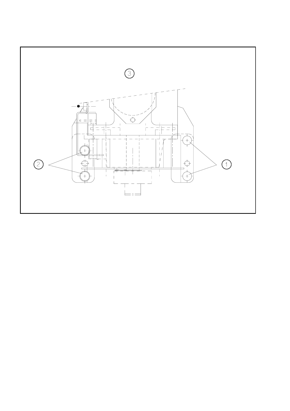
Loosen the four fixing screws for the IC head as shown in Fig. 8.7.1.
●
Remove the IC head and fix it to the mounting rack for the IC head.
8.7.4 Fit the IC Head
●
Fix the IC head in place using the 4 fixing screws. Please note that the screws are of different lengths! (see
Fig. 8.7.1 page 8 - 30)
●
Attach the power cables to the IC head board (see Fig. 8.2.2 page 8 - 8).
●
Reconnect the air hoses.
●
Edit the zero point correction values for the z and dr axes in the MA data.
●
Check the dynamic performance of the servo axes with reference to the Adjusting Instructions and adjust
the axes.
●
Measure the automatic placement machines with reference to the IC head.
From item number
Slotted head screw driver, set
Mounting rack for the IC head 00318295-01
SITEST program V
≥
203.000
Test box
Adjusting Instructions
From item number
IC head 00306366S02
8 IC Head SIPLACE 80S/F/G Service Manual
Edition 01/97
8 - 30
Fig. 8.7.1 Fixing screws for the IC head
Key to Fig. 8.7.1.
1 Fillister head screw M4 x 25 2 Fillister head screw M4 x 16
3 Viewed in the placement head mounting
direction

SIPLACE 80S/F/G Service Manual 8 IC Head
Edition 01/97
8 - 31
8.8 Servicing work that can only be carried out at the
factory
●
Servicing work on the z axis clamping device
This does not include replacement of the solenoid valve
●
Servicing work on the dr axis encoder unit
●
Removal of the head housing cover plate
❒