80S-15贴片机.pdf - 第288页
9 Revolver Head SIPLACE 80S/F/G Service Manual Edition 04/97 9 - 4 The SIP LACE p lacement machines are equ ipped with up to tw o revolv er head s depe nding on th e mac hine type: – The SIP LACE 80S machine with it s do…
SIPLACE 80S/F/G Service Manual 9 Revolver Head
Edition 04/97
9 - 3
9.1 Overview
The SIPLACE revolver placement head is equipped with 12 suction nozzles arranged in the form of a star
which pick up and mount components. The range of components extends from 0402 chips to SO28 compo-
nents, in other words components sized from 0.5 mm x 1.0 mm to 14 mm x 14 mm.
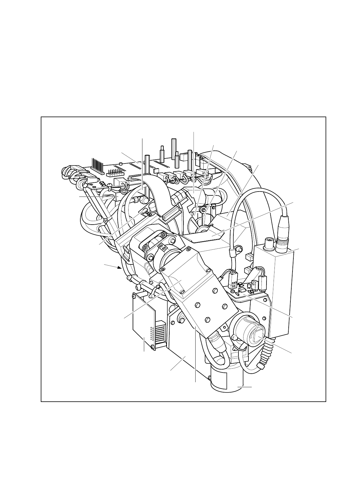
Fig. 9.1.1 SIPLACE revolver placement head - overall view
Conversion board 'small axis'
1710460-Y0005
Sz axis
cam disk
Absorber block
Lifting slide 16 mm
Cover
flap
Underneath the cover:
mech. centering station
and CRDL tester
(option)
Vacuum measuring
board
Illumination
control
PCB camera
PCB camera
Motor and tacho
star axis
PCB optical system
and illumination
Component camera
Transmitter housing
5x signal multiplication board
dp2 axis
Component optical system
and illumination
Lifting slide housing
(not visible)
Valve block
for "Forced
air" function
Motor, tacho and
incremental encoder of sz axis

9 Revolver Head SIPLACE 80S/F/G Service Manual
Edition 04/97
9 - 4
The SIPLACE placement machines are equipped with up to two revolver heads depending on the machine
type:
–
The SIPLACE 80S machine with its double gantry system has two revolver heads which operate indepen-
dently of one another.
–
The single gantry system of the SIPLACE 80F machine is fitted with one IC head and one revolver place-
ment head.
As a PCB is moved onto the board conveyor, the revolver head picks up 12 components from the components
conveyors with its suction nozzles arranged in the shape of a star. During one revolver head cycle the differ-
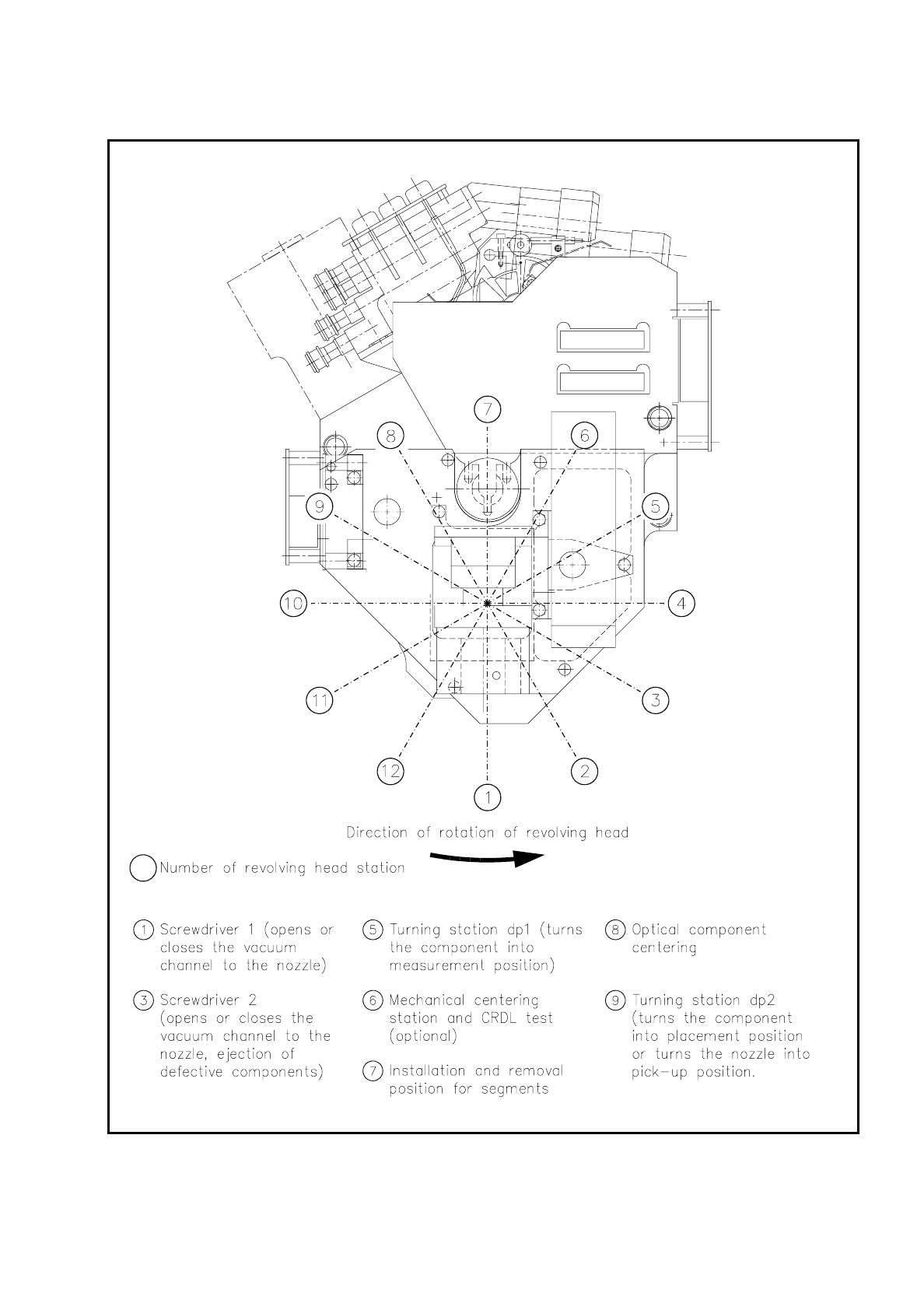
ent revolver head stations run through the following tasks (position of the stations, see Fig. 9.1.2).
Revolv. head station 1:
Pick-up cycle
The nozzle picks up a component. Here the vacuum line to the nozzle is opened
and the component picked up suction.
Placement cycle
The PCB which has come up in the meantime is mounted with the component which
is separated from the nozzle by a brief blast of compressed air. The nozzle is then
closed.
Revolv. head station 3: Faulty components are ejected and the nozzle closed.
Revolv. head station 5: The component is rotated into the measurement position for the CRDL test.
Revolv. head station 6: A CRDL test is carried out on the component.
If it is not possible to center components optically they will be centered mechanically
here.
Revolv. head station 8: The component is optically centered.
Revolv. head station 9:
Pick-up cycle
The nozzle is rotated into the pick-up position.
Placement cycle
The component is rotated into the placement position.
SIPLACE 80S/F/G Service Manual 9 Revolver Head
Edition 04/97
9 - 5
Fig. 9.1.2 Position number and function modules of the individual revolver head stations