80S-15贴片机.pdf - 第302页
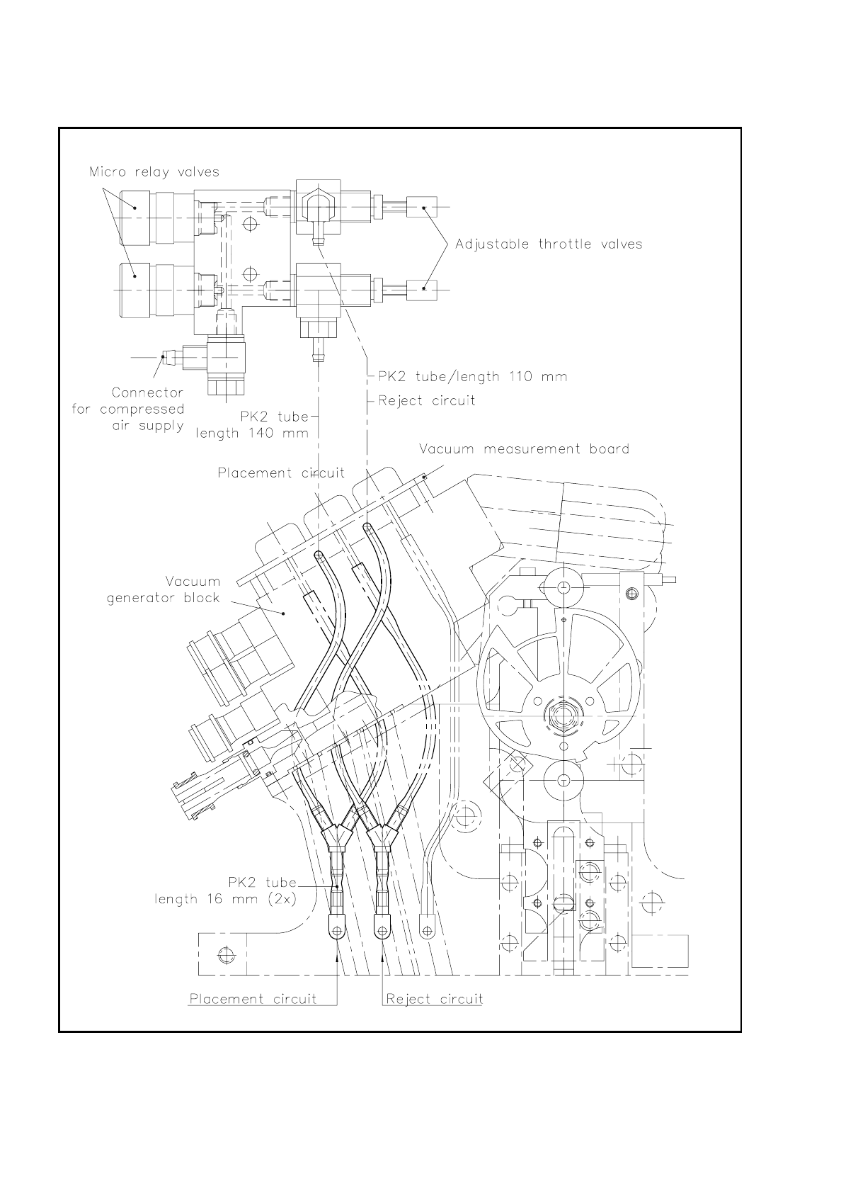
9 Revolver Head SIPLACE 80S/F/G Service M anual Edition 04/97 9 - 18 Fig. 9.4.1 Valve block, com plete, for the “Forced air“ function

SIPLACE 80S/F/G Service Manual 9 Revolver Head
Edition 04/97
9 - 17
9.4 Description of the Function "Forced Air"
With segment versions E5 and higher the components are no longer ejected from the nozzle with the pusher
but are separated from the nozzle by a short blast of compressed air.
This new method has been introduced mainly for the following reasons:
–
In the case of small components of size 0402 no reasonable ratio could be achieved technically between
the pusher needle diameter and the nozzle walls which would yield economically acceptable service life for
pusher needles and nozzles.
–
Precision of placement and placement performance can be improved with this new method.
–
From segment version E6, nozzles of different lengths can be used. In this way, with long nozzles the
placement shadow can be considerably reduced. In addition, this new technique removes the necessity of
changing pushers.
9.4.1 Mechanical Construction of the Function "Forced Air"
The valve block for the forced air function in the placement and ejection circuit is located directly below the
conversion board "small axis" 1710460-Y0005 (see Fig. 9.1.1) and is mounted on the head mounting of the
gantry. Fig. 9.4.1 shows the structure of the valve block. The compressed air is fed via the quick-release cou-
pling to the valve block. The micro relay valves feed the forced air into the placement circuit or ejection circuit
in order to separate the components from the nozzle.
The micro relay valve for the placement circuit is closest to the revolver placement head. Using the adjustable
restrictor valves you can adjust the strength of the forced air flow in the placement and ejection circuits. The
forced air is injected into the circuit in question by means of two fork distributors. Please refer to the adjust-
ment instructions for the on-times of the micro relay valves and the strength of the compressed air flow.
9 Revolver Head SIPLACE 80S/F/G Service Manual
Edition 04/97
9 - 18
Fig. 9.4.1 Valve block, complete, for the “Forced air“ function

SIPLACE 80S/F/G Service Manual 9 Revolver Head
Edition 04/97
9 - 19
9.4.2 Functional Sequence "Forced Air" during Placement of a Com-
ponent
The sz axis sinks. Once the sz axis has reached its bottom position, with the end signal the forced air valve is
opened for about 30 - 40 msec and the component set down on the PCB. Following this period of time the sz
axis begins moving back upwards. While it is so moving, screwdriver 1 is activated in order to close the seg-
ment vacuum duct with the sealing piston. With the end signal from screwdriver 1 the forced air valve is closed
again. As as the "sz axis in top end position" bero has responded the revolver head can cycle on.
9.4.3 Functional Sequence "Forced Air" during Ejection of a Compo-
nent
The forced air valve for the ejection circuit opens for about 60 msec in order to eject the component. The valve
then closes. The vacuum test is used to check whether the component has been ejected - in other words, the
vacuum value is measured while the segment is open. Following this test, screwdriver 2 closes the nozzle by
moving the sealing piston forwards into the segment. Once the bero of screwdriver 2 has finally given the end
signal the revolver head can cycle on.