80S-15贴片机.pdf - 第308页
9 Revolver Head SIPLACE 80S/F/G Service Manual Edition 04/97 9 - 24 Fig. 9.5. 2 shows th e struct ure of the lifting s lide hou sing . The vacuu m duc ts for the placeme nt, hold ing an d ejection circu its are shown as …
SIPLACE 80S/F/G Service Manual 9 Revolver Head
Edition 04/97
9 - 23
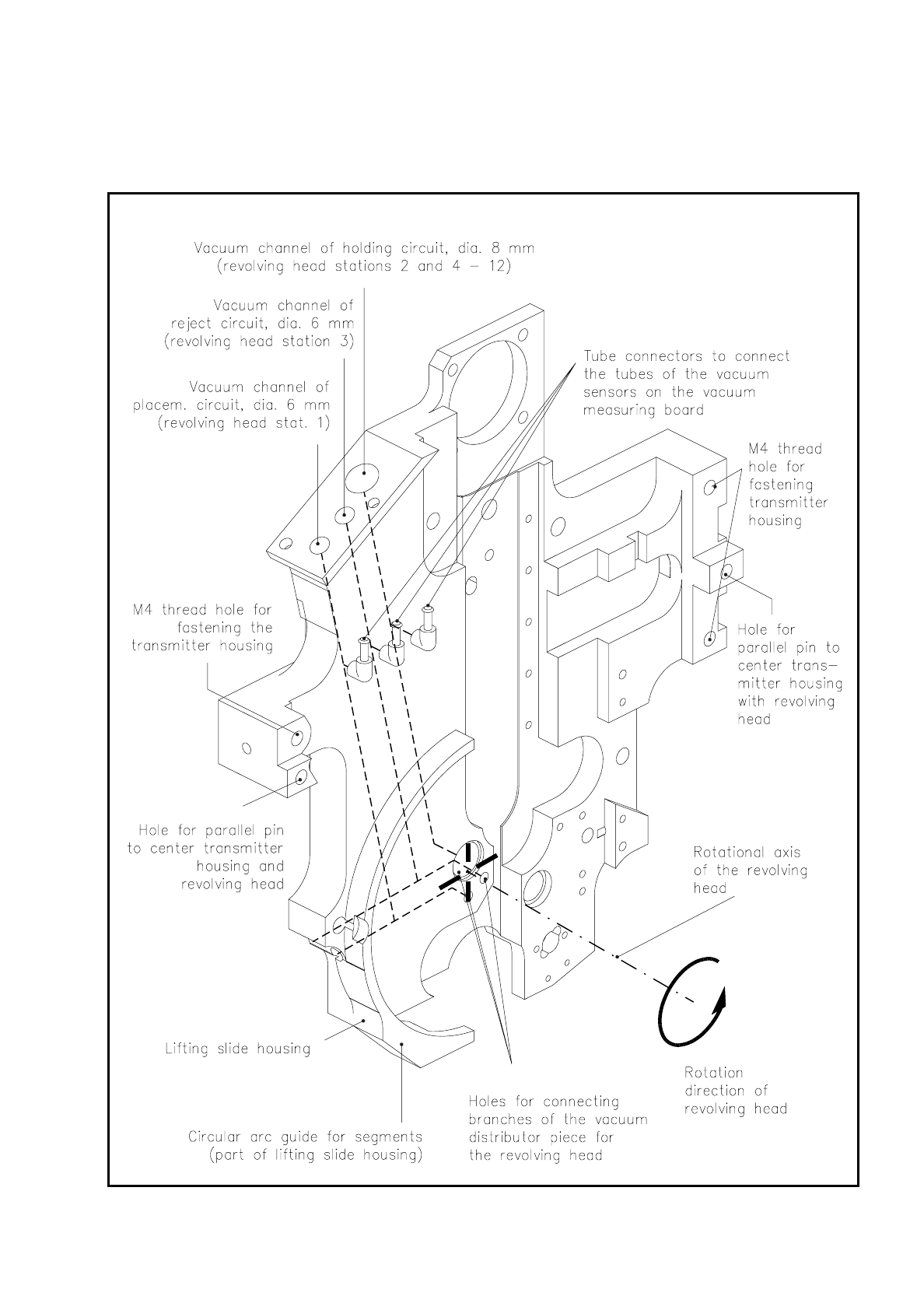
9.5.1 Lifting Slide Housing
Fig. 9.5.2 Lifting slide housing - holes of vacuum ducts

9 Revolver Head SIPLACE 80S/F/G Service Manual
Edition 04/97
9 - 24
Fig. 9.5.2 shows the structure of the lifting slide housing. The vacuum ducts for the placement, holding and
ejection circuits are shown as dashed lines.
The vacuum sensors on the vacuum measuring board are connected by hoses to the hose connections of the
individual vacuum ducts. In all there are 3 vacuum circuits:
–
Placement circuit
The placement circuit supplies revolver head station 1. At revolver head station 1 components are picked
up by the segments and set down on the PCB.
–
Ejection circuit
The ejection circuit supplies revolver head station 3 which is responsible for ejecting components and
checking nozzles for contamination.
–
Holding circuit
Revolver head stations 2 and 4 - 12 are connected to the holding circuit.
The vacuum sensors measure the vacuum values of the individual circuits. The analog values so obtained are
digitalized in the vacuum measuring board and compared with the specified vacuum values. If the values do
not lie within the permissible tolerances an error message will be issued.
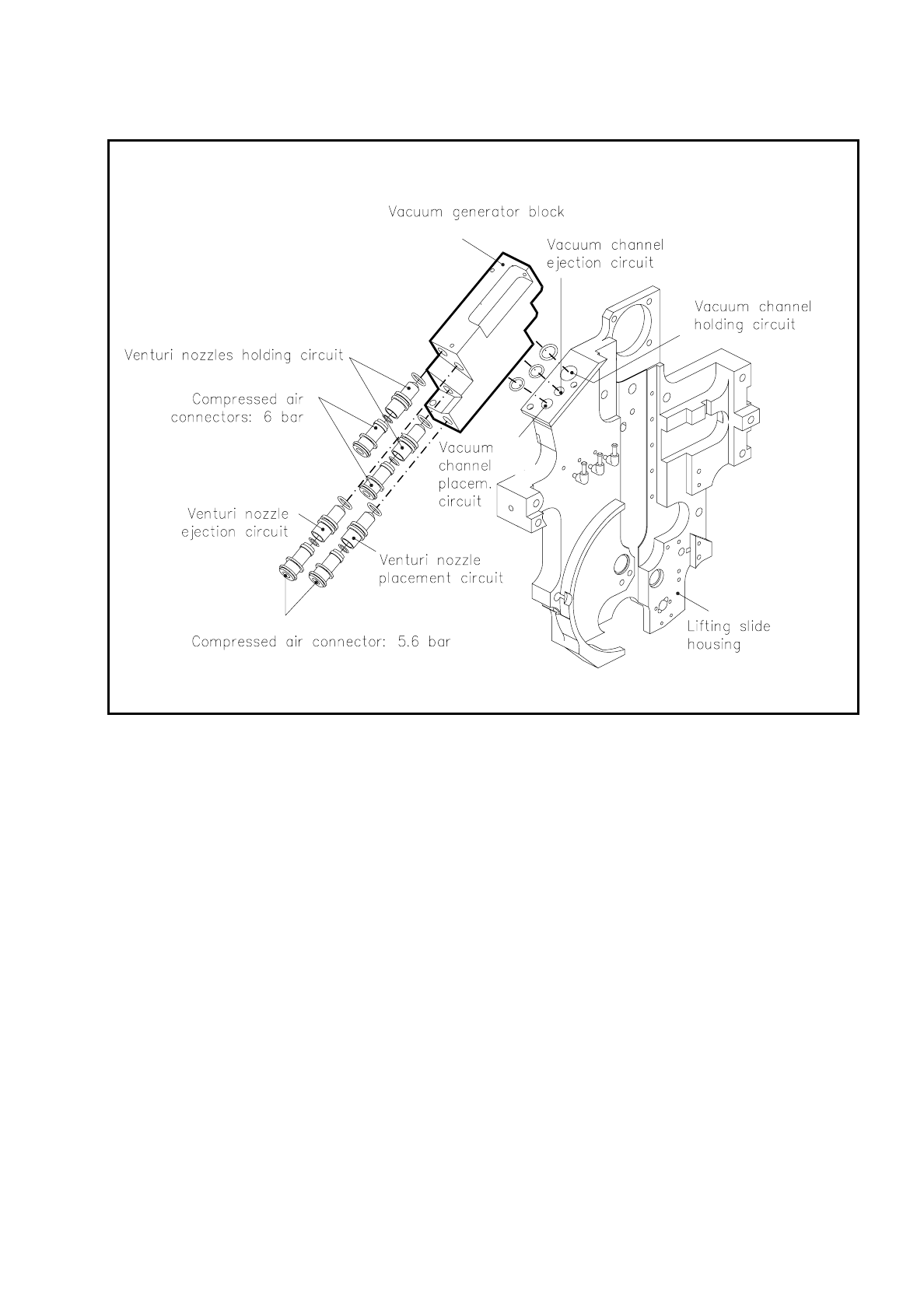
9.5.2 Vacuum Generator Block
The vacuum generator block generates the vacuum required for the holding circuit, placement circuit and
ejection circuit (see Fig. 9.5.3).
The vacuum is generated on the venturi principle.
Two Venturi nozzles are used for the holding circuit in order to obtain the vacuum values required for
operation for revolver head stations 2 and 4 to 12.
One venturi nozzle generates the vacuum for the placement circuit and thus for revolver head station 1, while
a second venturi nozzle generates the vacuum for the ejection circuit and thus for revolver head station 3.
The connected load at the compressed air supply is 5.6 bar per circuit. The final pressure in the individual
vacuum ducts is 900 mbar.
With the aid of the vacuum in the individual circuits the components are sucked so strongly to the individual
nozzles that they remain in their precisely specified position during pick-up, rotation and placement.
The vacuum duct junctions between the vacuum generator block and the lifting slide housing are sealed with
o rings. The vacuum generator block can be detached easily from the lifting slide housing once two M3-hexa-
gon socket-head screws have been unscrewed.
SIPLACE 80S/F/G Service Manual 9 Revolver Head
Edition 04/97
9 - 25
Fig. 9.5.3 Vacuum generator block