80S-15贴片机.pdf - 第311页
SIPLACE 80S/F/G Service Manual 9 Revolver Head Edition 04/97 9 - 27 Fig. 9.5.5 V acuum measuring board The three measu rement c ircuits are temperatu re-com pensa ted. With the ho ldin g ci rcui t , only a thresh old val…
9 Revolver Head SIPLACE 80S/F/G Service Manual
Edition 04/97
9 - 26
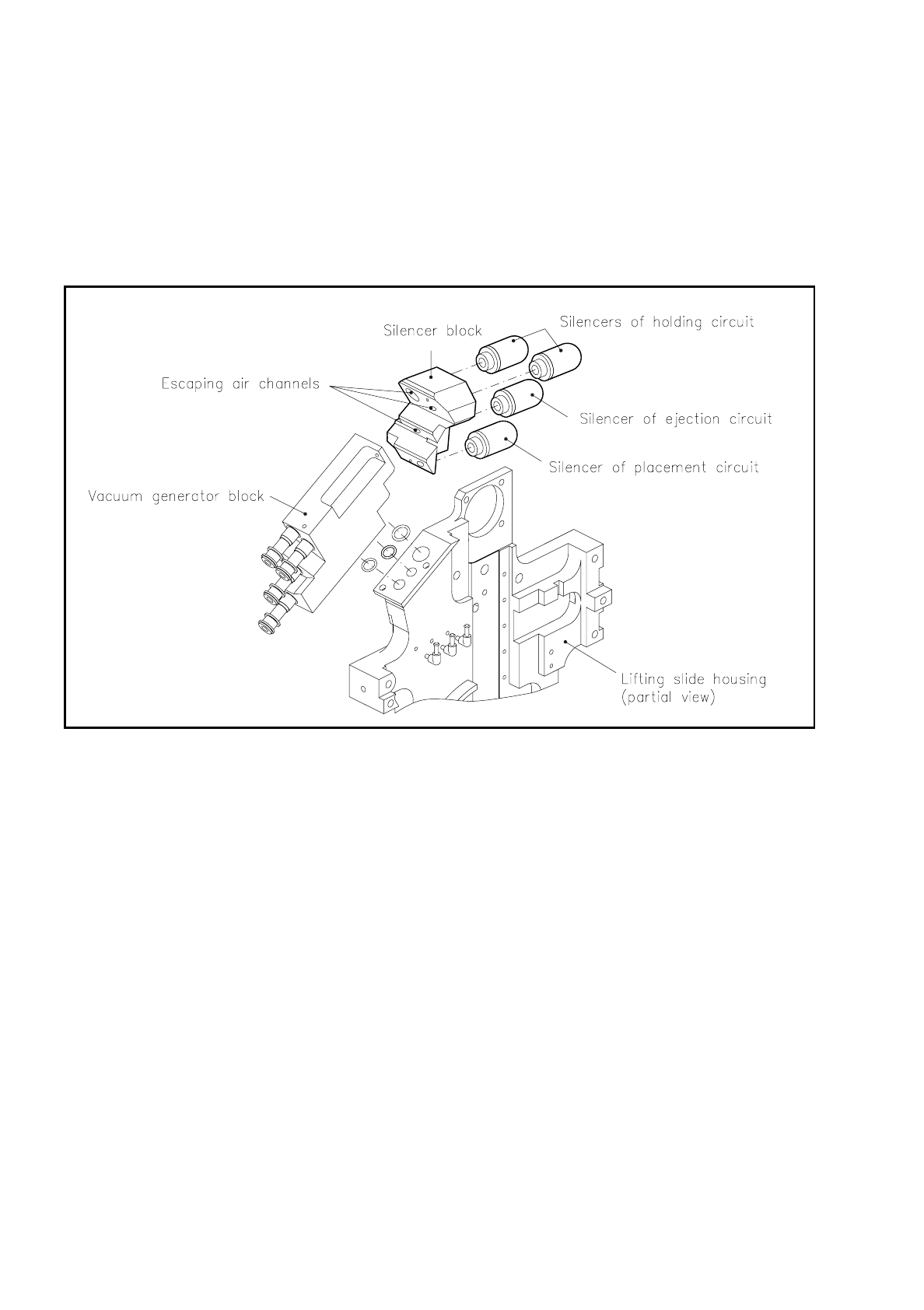
9.5.3 Silencer Block
The silencer block with its four silencers reduces the noise of the air escaping from the venturi nozzles. It is
fastened to the vacuum generator block with two M3 hexagon socket-head screws.
The silencers have an M8 thread and can therefore be replaced easily when this is necessary.
Fig. 9.5.4 Silencer block
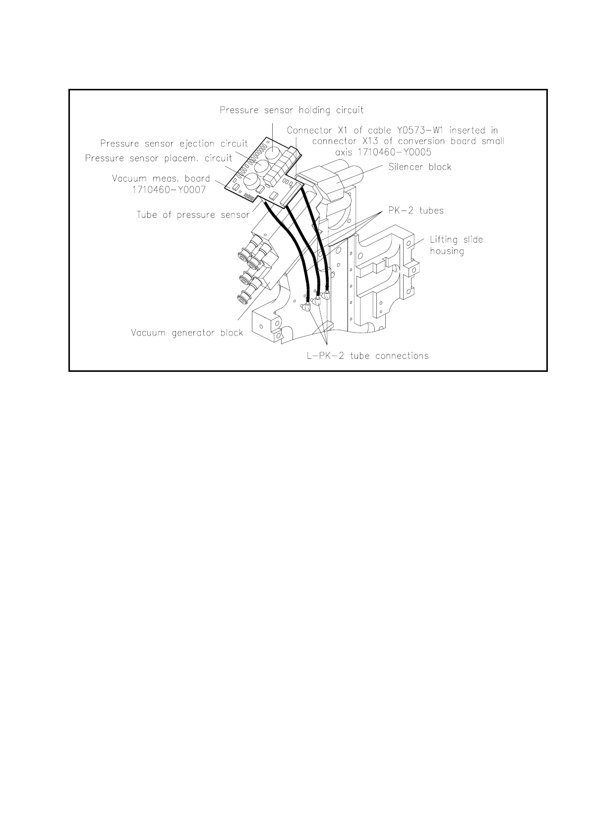
9.5.4 Vacuum Measuring Board
The vacuum measuring board 1710460-Y0007 is fastened to the vacuum generator block with two M2-slotted
screws and isolating spacer.
The sensor tubes of the individual pressure sensors are connected with PK-2 hoses to the L-PK-2 hose con-
nections for the purpose of measuring the pressure in the vacuum ducts of the holding, placement and ejec-
tion circuits.
SIPLACE 80S/F/G Service Manual 9 Revolver Head
Edition 04/97
9 - 27
Fig. 9.5.5 Vacuum measuring board
The three measurement circuits are temperature-compensated.
With the
holding circuit
, only a threshold value comparison is made of the current vacuum value with the
actual value for monitoring purposes. If there is a drop below the vacuum threshold value set when the
machine went into service then the output of this monitoring circuit will alarm the machine controller. An error
message will appear on the station computer monitor.
With the placement circuit and
ejection circuit
the current vacuum values are determined in numerical form
by the computer. The machine controller sends an 8-bit data word to the digital-to-analog converter on the
vacuum measuring board. The electrical circuit diagram for the vacuum measuring board is included in the cir-
cuit diagrams folder, Section 3.11, for the SIPLACE 80S machine. The comparator of the vacuum circuit in
question compares the two analog signals of the actual and the D/A converter values and then signals the
machine controller as to whether the actual value is above or below the desired value. In this way the precise
vacuum value is determined by successive approximation. Comparison of the actual value so obtained with
the line computer data will then provide information on the vacuum states obtaining in each case, and which
are described below, and actions thereby triggered.
9.5.4.1 Determination of the Vacuum Values during the Reference Run
In the reference run the vacuum values are determined for the individual segments for the pick-up and place-
ment circuit and for the ejection circuit at revolver head stations 1 and 3. The measured values are taken into
the MA data of the placement program. Threshold values also required are calculated.

9 Revolver Head SIPLACE 80S/F/G Service Manual
Edition 04/97
9 - 28
The following vacuum values are determined:
1. Checking the Vacuum in the Holding Circuit
A check is made as to whether the vacuum value of the holding circuit is better than the specified threshold
value.
2. Vacuum value "Segment sealed" in the pick-up and placement circuit
This value is determined for every segment in revolver head station 1. Firstly the value is determined for
each of the two positions of the sealing piston: segment opened and segment closed. Next, the two values
are compared and a decision is made as to whether the segment must be closed. These two values pro-
vide the "measured vacuum clearance between open and closed segment" (see Fig. 9.5.6).
3. Vacuum value "Component picked up" with large nozzles in the pick-up and placement circuit
This value is determined in revolver head station 1 for each segment with the corresponding nozzle. The
sealing piston is retracted: in other words, the segment is opened. On the basis of this measurement a
threshold value "Maximum vacuum value for the open segment" is defined (see Fig. 9.5.6).
4. Vacuum value "good and bad nozzle contact" for components in the ejection circuit
In revolver head station 3 (ejection circuit) the vacuum values are determined for normal nozzle sizes for
each segment with the segment open and closed. It is then decided whether the segment must be closed.
A check is made at the same time whether the clearance values with the segment open and closed exceed
the minimum value specified by the line computer. These values are used in turn to calculate the threshold
values for "Good and bad nozzle contact" and added to the MA data (see Fig. 9.5.6).