80S-15贴片机.pdf - 第318页
9 Revolver Head SIPLACE 80S/F/G Service Manual Edition 04/97 9 - 34 9.5. 5.3 SZ Axis Drive Fig. 9.5. 8 shows th e drive for the sz axis, whi ch power s the li fting move ment of the li fting sli de. The b ero signals whe…
SIPLACE 80S/F/G Service Manual 9 Revolver Head
Edition 04/97
9 - 33
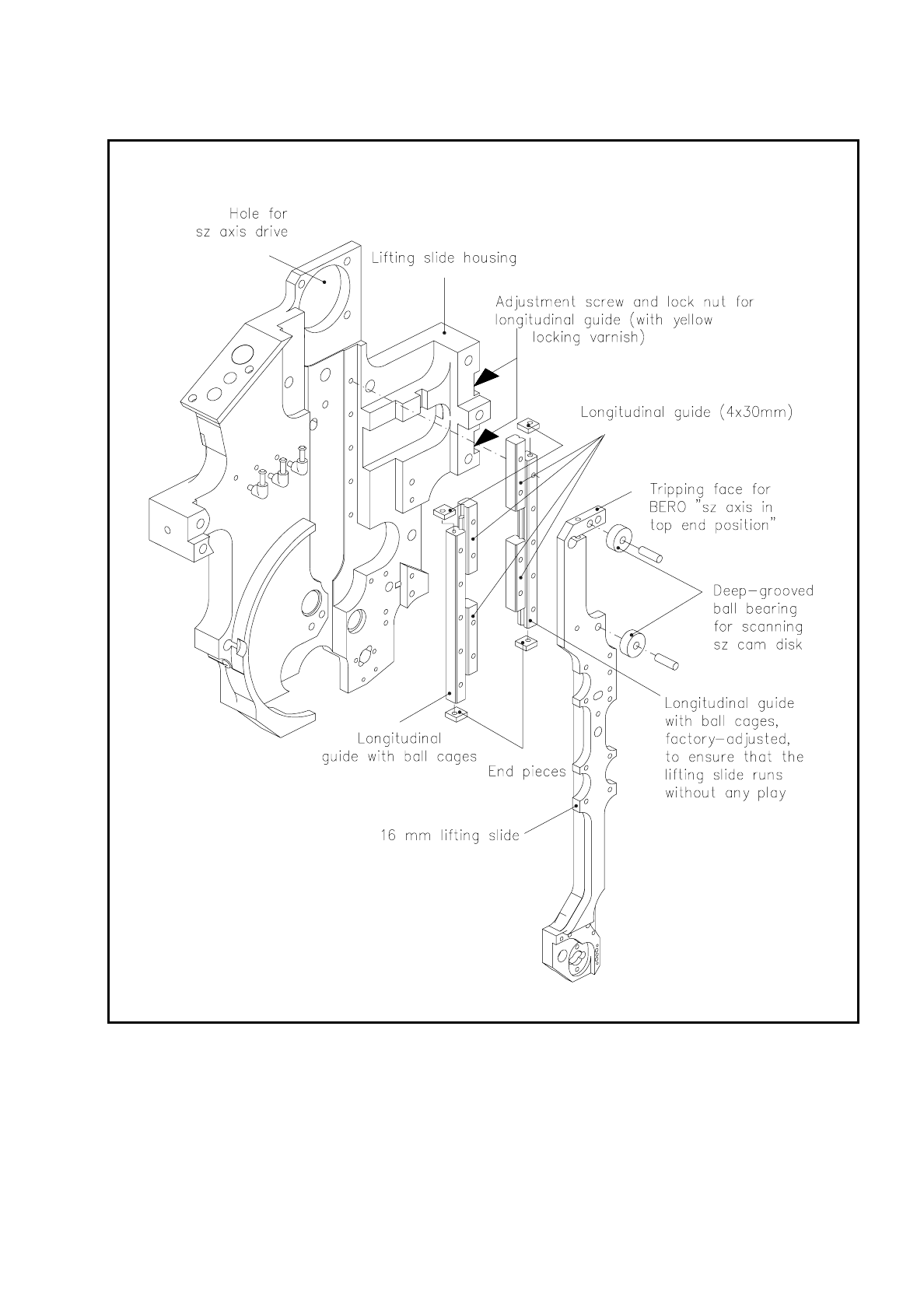
Fig. 9.5.7 16 mm lifting slide and longitudinal guide
9 Revolver Head SIPLACE 80S/F/G Service Manual
Edition 04/97
9 - 34
9.5.5.3 SZ Axis Drive
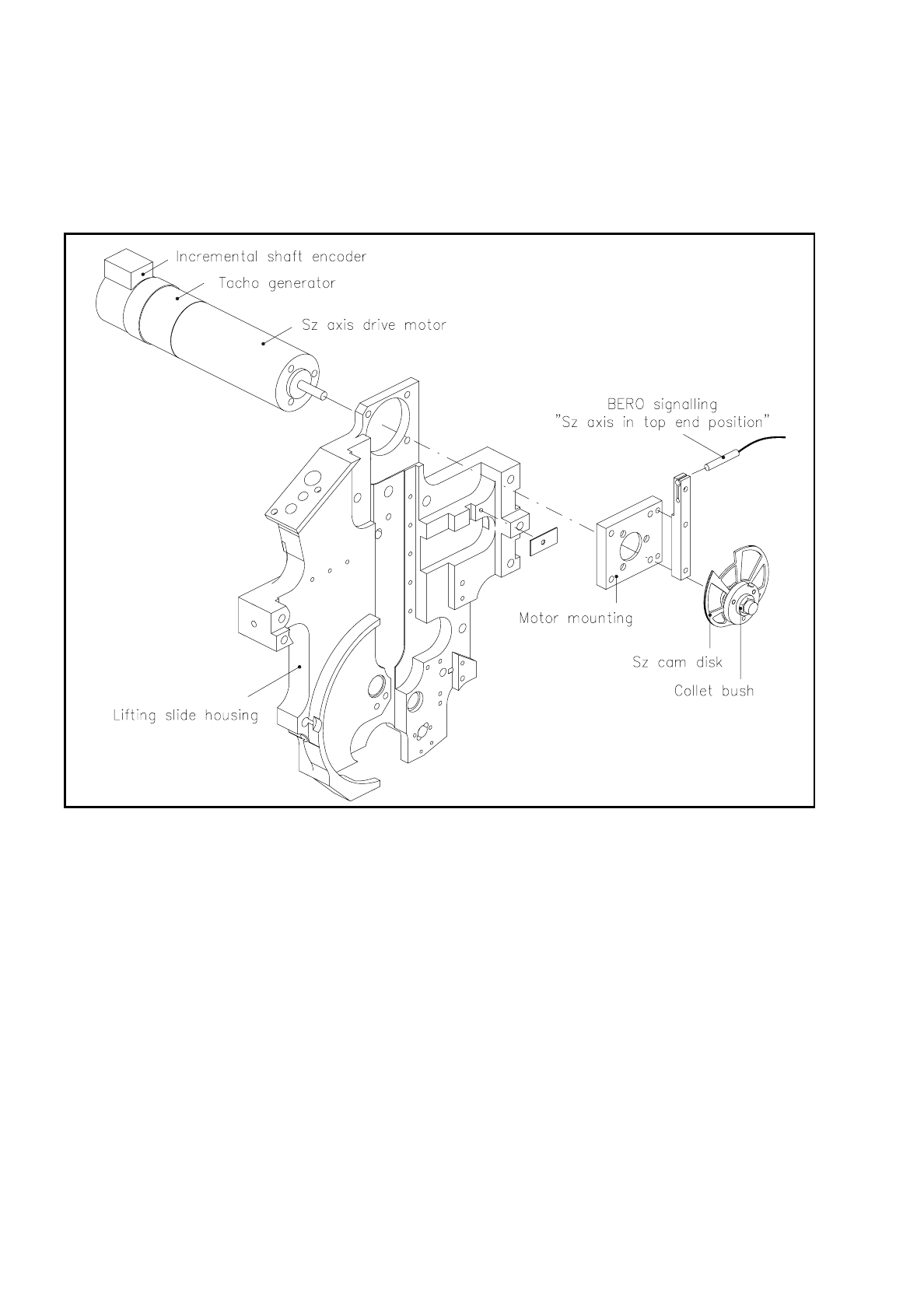
Fig. 9.5.8 shows the drive for the sz axis, which powers the lifting movement of the lifting slide. The bero
signals when the lifting slide has reached the top end position.
Fig. 9.5.8 sz axis drive
The sz axis drive motor is a direct current servo motor with integrated tachometer generator and incremental
shaft encoder. The drive motor is fastened to the motor mounting with three M3 slotted screws, and this
mounting in its turn is screwed to the lifting slide housing with four M3 hexagon socket-head screws.
In addition, the holder for the bero which signals "sz axis in top end position" is fastened to the motor mount-
ing. A collet bush holds the sz cam disk on the drive shaft of the sz axis drive motor.
The travel of the sz axis for picking up and inserting a component is determined by the height of the compo-
nent. A continuous comparison of the actual and set heights of the component permits the travel speed of the
sz axis to be adapted to circumstances and the component is picked up from the conveyor with sensor stop
and mounted on the PCB.
SIPLACE 80S/F/G Service Manual 9 Revolver Head
Edition 04/97
9 - 35
9.5.5.4 Segment Claw
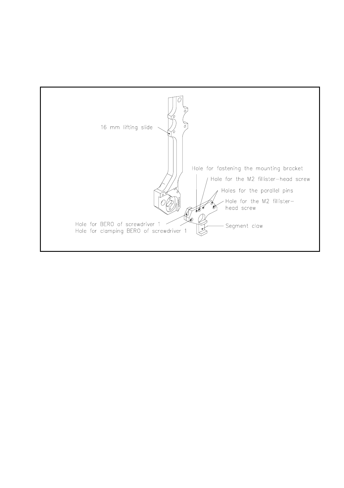
The segment claw is fastened by two M2 fillister head screws to the bottom end of the 16 mm lifting slide. Two
parallel pins center the segment claw on the lifting slide.
Fig. 9.5.9 Segment claw
In revolver head station 1 the ball bearing which runs on the circular arc guide and link runs into the segment
claw. This allows the lifting slide to precisely position the segment vertically.
9.5.6 Screwdriver Unit 1 (Picking Up / Placement)
Screwdriver unit 1 (see Fig. 9.5.10) moves the sealing plunger of the segment. It is built into the bottom end of
the lifting slide. To pick up or insert a component it is lowered vertically with the sz axis.
During the pick-up procedure, screwdriver unit 1 is activated as soon as the end signal of the sz axis has been
triggered - in other words, as soon as the nozzle has been set down on the component to be picked up. Imme-
diately following this activation, the screwdriver rotates by 180°. The sealing plunger is retracted at the same
time, the vacuum duct opened and the component sucked up into place.
For placement the lifting slide together with screwdriver unit 1 sinks. Once the component is in position on the
PCB, the end signal of the sz axis will be given. The forced air valve for setting down components from the
nozzle is opened and the component is set down. After a waiting time of 30 to 40 msec (with the booster ver-
sion about 12 ms) the lifting slide moves upwards. Screwdriver 1 moves the sealing plunger towards the noz-
zle and closes the segment. When the end signal of screwdriver 1 is given the forced air valve closes and the
placement circuit is evacuated.