80S-15贴片机.pdf - 第320页
9 Revolver Head SIPLACE 80S/F/G Service Manual Edition 04/97 9 - 36 Fig. 9.5.10 Sc rewdriver unit 1 Scre wdriv er un it 1 co nsis ts of t he fo llowi ng co mponen ts: – drive m otor – gearwhee l with sto p nippl e – stop…
SIPLACE 80S/F/G Service Manual 9 Revolver Head
Edition 04/97
9 - 35
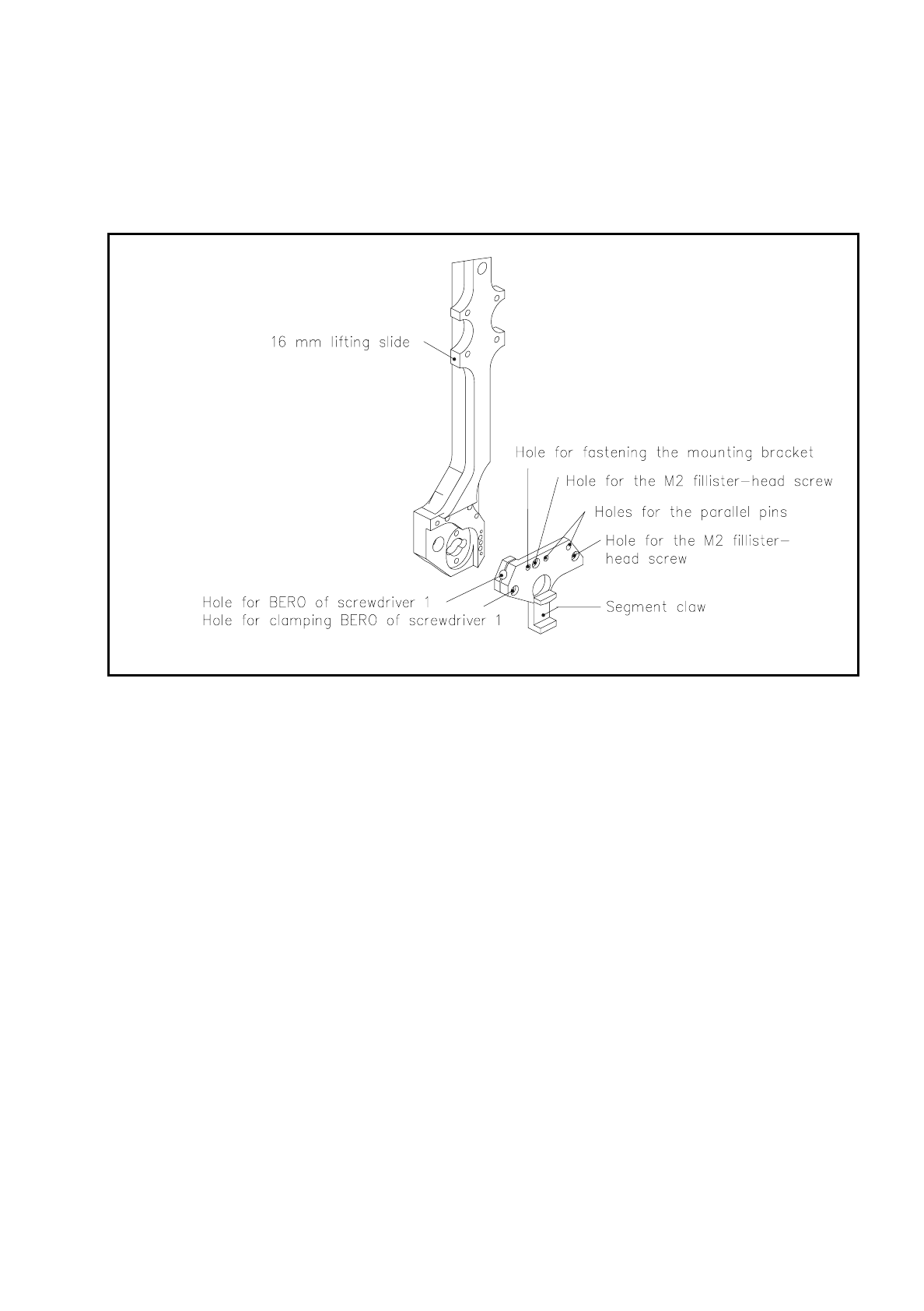
9.5.5.4 Segment Claw
The segment claw is fastened by two M2 fillister head screws to the bottom end of the 16 mm lifting slide. Two
parallel pins center the segment claw on the lifting slide.
Fig. 9.5.9 Segment claw
In revolver head station 1 the ball bearing which runs on the circular arc guide and link runs into the segment
claw. This allows the lifting slide to precisely position the segment vertically.
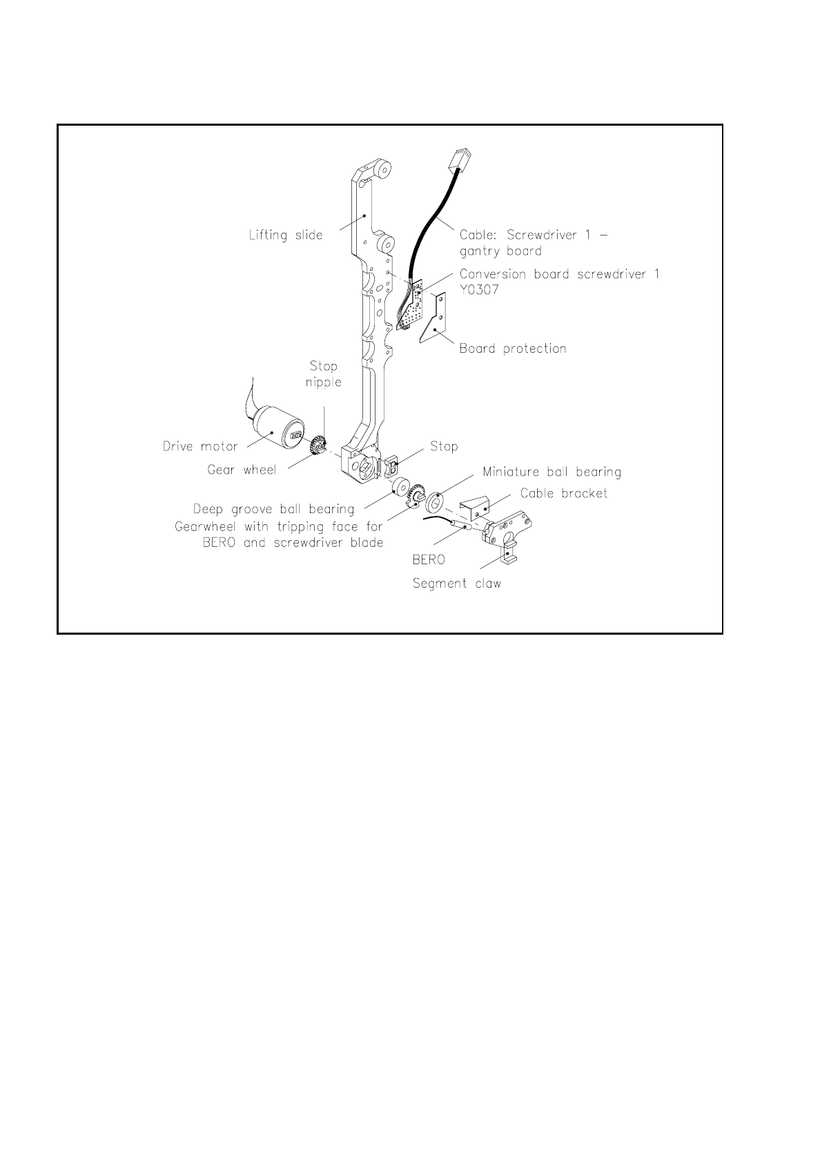
9.5.6 Screwdriver Unit 1 (Picking Up / Placement)
Screwdriver unit 1 (see Fig. 9.5.10) moves the sealing plunger of the segment. It is built into the bottom end of
the lifting slide. To pick up or insert a component it is lowered vertically with the sz axis.
During the pick-up procedure, screwdriver unit 1 is activated as soon as the end signal of the sz axis has been
triggered - in other words, as soon as the nozzle has been set down on the component to be picked up. Imme-
diately following this activation, the screwdriver rotates by 180°. The sealing plunger is retracted at the same
time, the vacuum duct opened and the component sucked up into place.
For placement the lifting slide together with screwdriver unit 1 sinks. Once the component is in position on the
PCB, the end signal of the sz axis will be given. The forced air valve for setting down components from the
nozzle is opened and the component is set down. After a waiting time of 30 to 40 msec (with the booster ver-
sion about 12 ms) the lifting slide moves upwards. Screwdriver 1 moves the sealing plunger towards the noz-
zle and closes the segment. When the end signal of screwdriver 1 is given the forced air valve closes and the
placement circuit is evacuated.
9 Revolver Head SIPLACE 80S/F/G Service Manual
Edition 04/97
9 - 36
Fig. 9.5.10 Screwdriver unit 1
Screwdriver unit 1 consists of the following components:
–
drive motor
–
gearwheel with stop nipple
–
stop for limiting rotation
–
deep-grooved ball bearing
–
gearwheel with tripping face for the bero
–
miniature ball bearing
–
bero with cable bracket
–
conversion board "Screwdriver 1" 1710491 - Y0307 with plug connection to the conversion board "Head"
1710491-Y0303
A d.c. motor controls the rotation of the screwdriver 1 which moves the sealing plunger. The motor is fitted
from the rear side of the lifting slide with 2 fillister head screws M1.6.
SIPLACE 80S/F/G Service Manual 9 Revolver Head
Edition 04/97
9 - 37
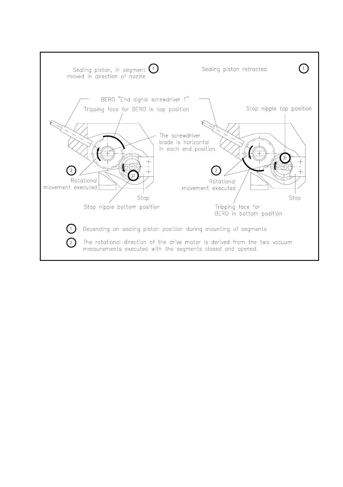
Fig. 9.5.11 Determination of the direction of rotation of the screwdriver unit 1
On the motor shaft sits the gearwheel with stop nipple which limits rotational movement at the stop to 180° in
each case. The stop is screwed to the segment claw.
The sealing piston is held in the respective end position by means of holding current. The screwdriver itself is
a gearwheel with a turned-on shaft. The shaft at one end is mounted in a miniature ball bearing, at the other in
a deep-grooved ball bearing. The motor pinion meshes with the teeth of the gearwheel.
The shaft end pointing to the segment claw is flattened on two opposite sides and forms the screwdriver unit
blade. Accordingly, the screwdriver engages with the slot in the eccentric shaft of the segment in the revolver
head station 1. For an area extending over 90° the gearwheel has no teeth (see Fig. 9.5.10). When the
screwdriver rotates, this section activates the bero in the segment claw. It sends the end signal when the
screwdriver has completed its rotation.
The bero cable runs in the recess in the lifting slide to the screwdriver 1 conversion board and from there is
routed to the plug at the "Small axis" conversion board 1710460-Y0005. A cable bracket above the segment
claw protects it against being damaged when the sz axis moves.