80S-15贴片机.pdf - 第333页
SIPLACE 80S/F/G Service Manual 9 Revolver Head Edition 04/97 9 - 49 9.6.2 Rotational Drive of the Revolver Head The pos ition ing sys tem of dR axis (revo lver he ad axis ) is a closed- loop co ntrol circu it. This circu…
9 Revolver Head SIPLACE 80S/F/G Service Manual
Edition 04/97
9 - 48
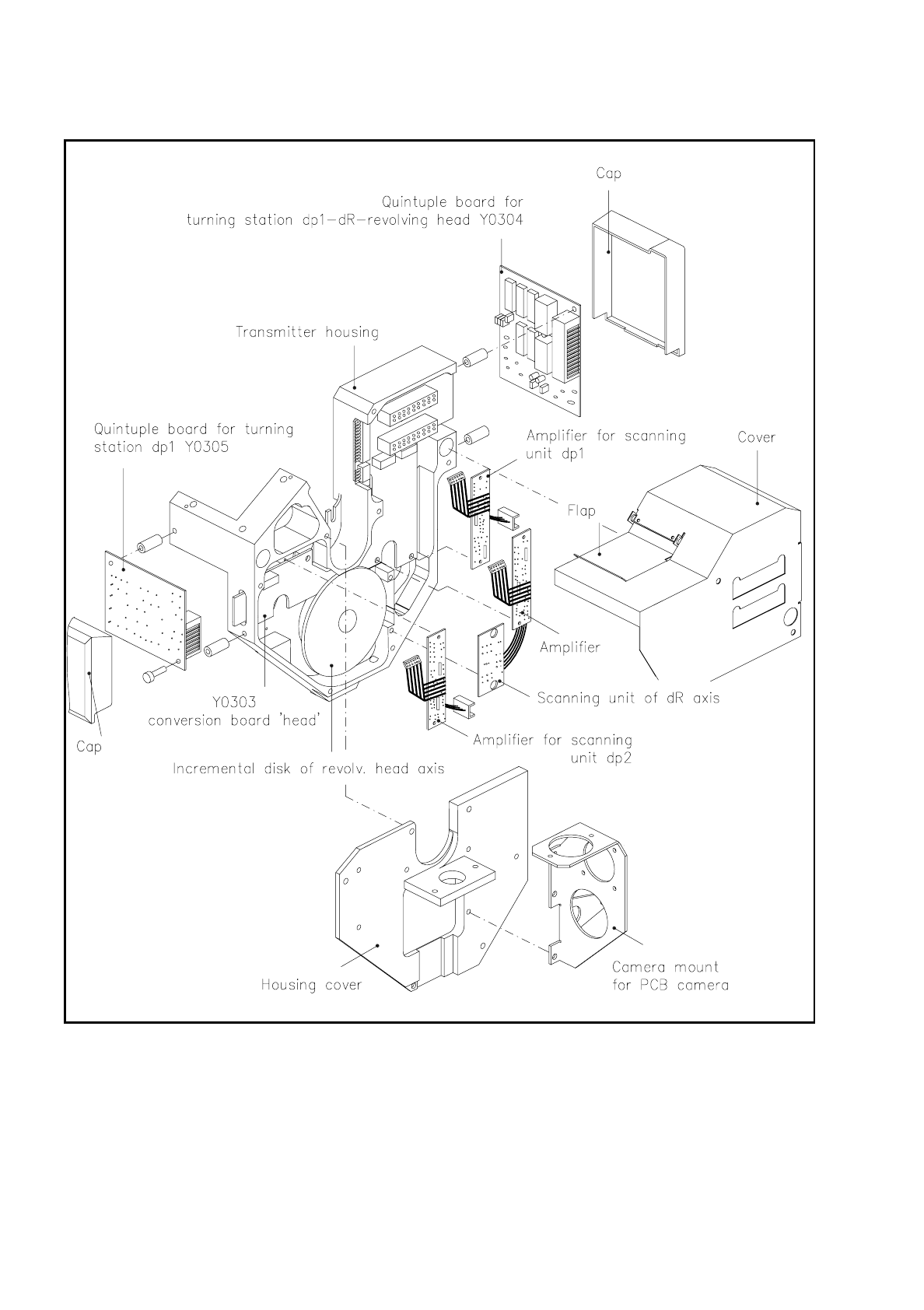
Fig. 9.6.4 Assemblies of the encoder housing “complete“ - front view

SIPLACE 80S/F/G Service Manual 9 Revolver Head
Edition 04/97
9 - 49
9.6.2 Rotational Drive of the Revolver Head
The positioning system of dR axis (revolver head axis) is a closed-loop control circuit. This circuit includes the
following components:
–
machine controller and axis controller card in the slide-in control unit
–
servo amplifier in the servo unit
–
rotational drive of the revolver head
–
encoder of the revolver head
The machine controller supplies the axis controller with the machine data for cycling on the revolver head.
This in turn operates the servo amplifier which supplies the drive motor with the voltage and current values it
needs. The encoder returns the current position of the revolver head to the axis controller. Here the actual and
desired position data of the revolver head are compared. The axis controller activates the servo amplifier until
the setpoint position is reached. The tachometer generator of the drive motor supplies the servo amplifier with
an analog signal which varies in accordance with speed. With the aid of this signal the output voltage and cur-
rent of the servo amplifier are stabilized for the drive motor.
The rotational drive cycles the revolver head on by the steps specified by the axis controller - in other words,
the segments are in each case transported on from revolver head station to revolver head station.
The rotational drive of the revolver head consists of the following components:
–
direct current servo motor with built-on tachometer generator
–
toothed belt pulley, 21 teeth
–
endless toothed belt
–
toothed belt pulley, 112 teeth
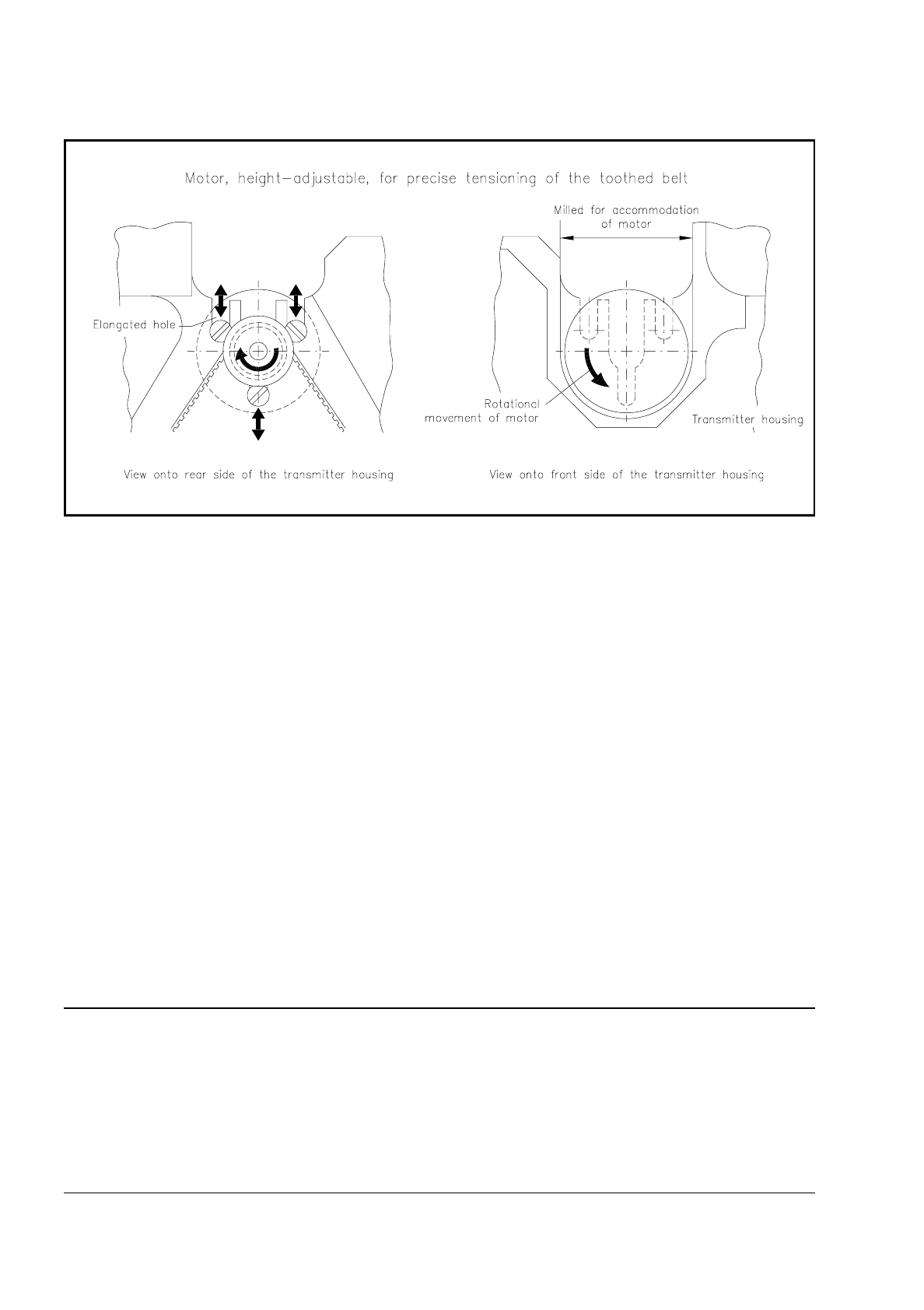
The drive motor is fastened with three M3-slotted screws to the encoder housing. The holes in the
encoder housing for the fastening screws take the form of slots so that the tension of the drive belt can be set
precisely.
The drive motor rotates anti-clockwise, looking from the front of the encoder housing.
9 Revolver Head SIPLACE 80S/F/G Service Manual
Edition 04/97
9 - 50
Fig. 9.6.5 Mounting of the revolver head drive motor
9.6.3 Turning Station dp1
Turning station dp1 rotates the component picked up by the segment into the position required for CRDL test-
ing. CRDL testing is carried out at the mechanical centering station of revolver head station 5.
Turning station dp1 is fastened with two M3-hexagon socket-head screws to the encoder housing. The adjust-
ment plate (see Fig. 9.6.3) located between them determines the separation of station and encoder housing.
The principle Components of the turning station:
–
housing of the turning station
–
feed motor for swinging the belt pulley in and out of position
–
motor-tacho combination for driving the belt pulley and thus the friction wheel of the segment
–
toothed lever with driver, deep-grooved ball bearing and belt pulley
–
o-ring
–
bero with locking ring
–
opto-electronic scanner unit for the incremental disk of the segment
–
conversion board "Rotate nozzle" 1710491-Y0306
NOTE
Turning stations dp1 in revolver head station 5 and dp2 in revolver head station 9 are identical in design. How-
ever
under no circumstances
remove one of the adjustment plates when replacing the turning stations. The
adjustment plate thickness and adjustment have been selected at the factory so that the turning stations are
dimensionally adjusted to the nozzle midpoint with respect to the encoder housing and the dimensions of the
rotating head. This means that the turning stations can be easily replaced without the need for additional
mechanical setting work.