80S-15贴片机.pdf - 第349页
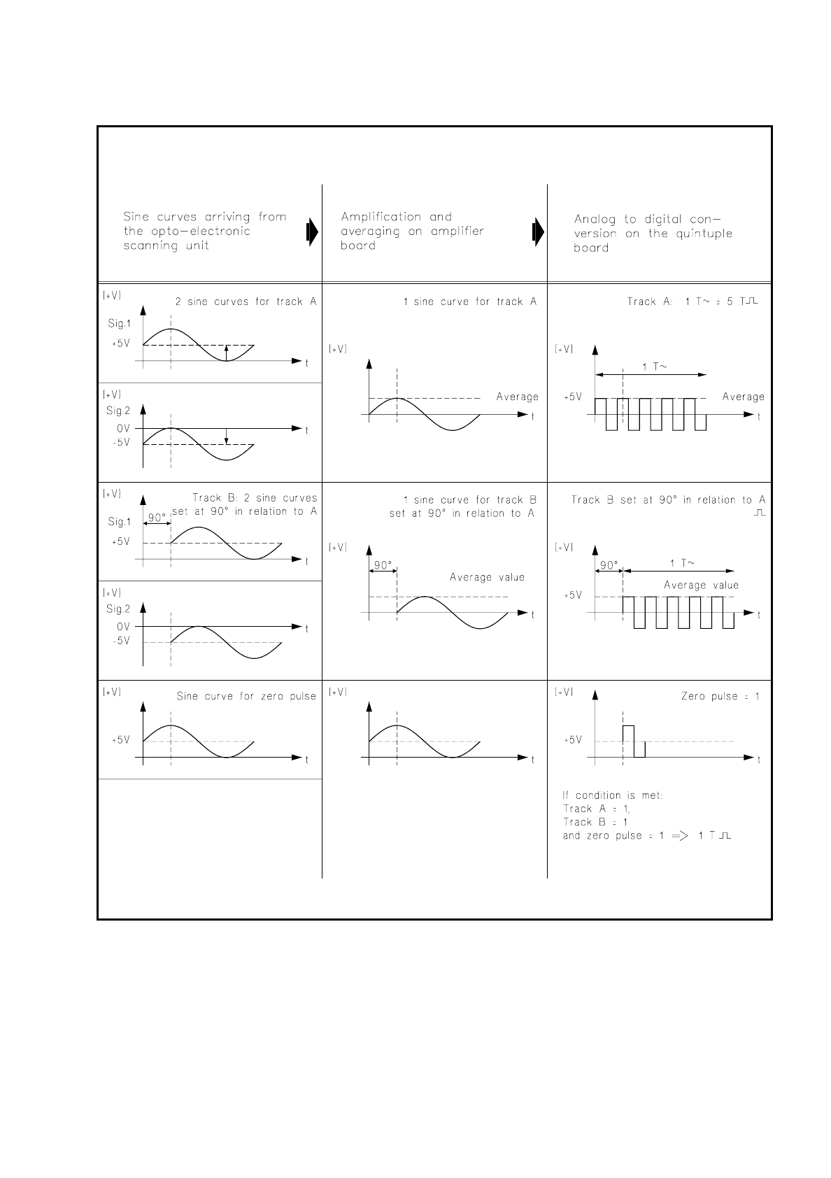
SIPLACE 80S/F/G Service Manual 9 Revolver Head Edition 04/97 9 - 65 Fig. 9.6.15 Conversion of the sinusoidal curves of the dp1, dp2 and dR axes and track signals into square-wave pulses

9 Revolver Head SIPLACE 80S/F/G Service Manual
Edition 04/97
9 - 64
9.6.8 Amplifier Boards for the dp1, dp2 and dR Axes
The amplifier boards for the dp1, dp2 and dR axes are fastened with spacer pins to the conversion board
"Head". These boards amplify the sinusoidal signals coming from opto-electronic scanner units. Each scanner
unit supplies five sinusoidal signals:
two for track A
two for track B (rotated by 90° with respect to track A)
one for the zero pulse
For each track the mean value is formed from the two arriving sinusoidal signals and conditioned for the quin-
tuple board. With the zero pulse no averaging takes place (see Fig. 9.6.15).
NOTE
The opto-electronic scanner unit and the amplifier board are set to one another in the factory and can there-
fore only be replaced as a unit. As a rule this unit will be replaced in the factory.
9.6.9 Quintuple Boards
The quintuple boards are located on the outside of the encoder housing by the conversion board "Head" (see
Fig. 9.6.14). Board 1710491-Y0304 converts the analog track and zero pulse signals coming from the ampli-
fier boards into digital pulses and quintuples, or multiplies them by five. It is connected via plug X3 to the con-
version board "Head".
Board 1710491-Y0305 converts the analog track and zero pulse signals coming from the amplifier boards into
digital pulses and quintuples them. It is connected by plug X5 to the conversion board "Head". Fig. 9.6.15
shows the signal processing which the track signals of the dp1, dp2 and dR axes undergo.
SIPLACE 80S/F/G Service Manual 9 Revolver Head
Edition 04/97
9 - 65
Fig. 9.6.15 Conversion of the sinusoidal curves of the dp1, dp2 and dR axes and track signals into square-wave pulses

9 Revolver Head SIPLACE 80S/F/G Service Manual
Edition 04/97
9 - 66
9.6.10 Incremental Shaft Encoder of the dR Axis
The incremental shaft encoder of the dR axis supplies information concerning the current position of the
revolver head when the revolver head cycles the segments on from station to station. Once the required posi-
tion is reached the rotational movement of the revolver head is stopped. The position regulator then fixes the
revolver head in this position.
The resolution of the electronic positioning system of the dR axis is 200 digits per degree.
The incremental shaft encoder of the dR axis basically consists of the following components (see Fig. 9.6.16):
–
glass disk with 3600 lines for the position track and a zero pulse track
–
bearing bush: the glass disk is glued to the bearing bush in the factory.
–
2 deep-grooved ball bearing
–
light source with lens system and light source masks with 5 through-holes as encoder
–
opto-electronic scanning with 5 phototransistors
●
2 each for position tracks A and B
●
one for the zero pulse track
–
M5 hexagon socket-head screw for mounting the revolver head on the incremental shaft encoder. The
hexagon socket-head screw is varnished after the revolver head is fitted in the factory.
NOTE
During all servicing work, make sure that the glass disk does not get dirty or come into contact with solvents
otherwise there will be counting errors and thus positioning errors.
NOTE
As a rule it will only be possible to replace the revolver head in the factory since the varnished M5 hexagon
socket-head screw has to be removed.