80S-15贴片机.pdf - 第359页
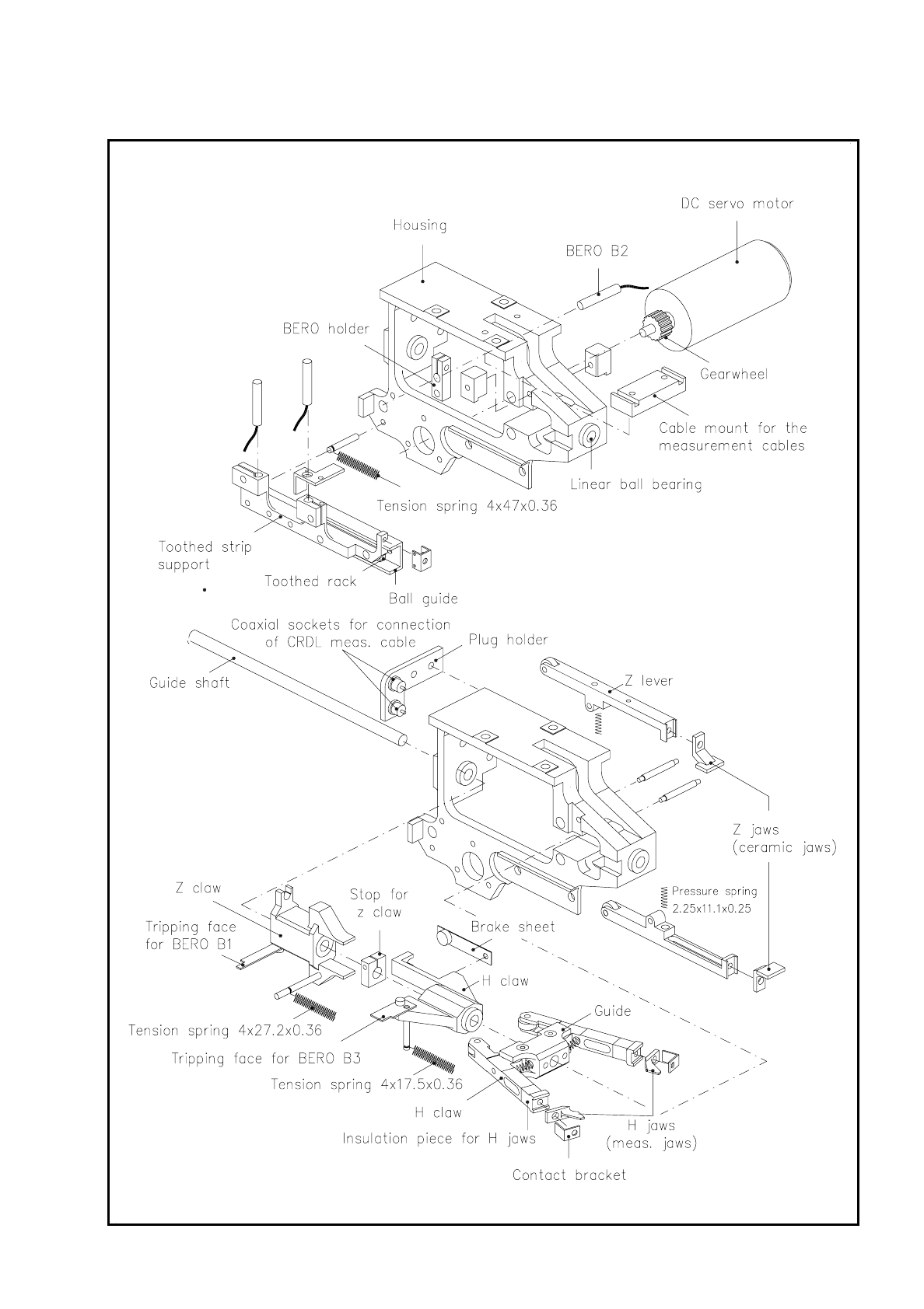
SIPLACE 80S/F/G Service Manual 9 Revolver Head Edition 04/97 9 - 75 Fig. 9.7.5 Structure of the mechanical centering s tation (exploded view)
9 Revolver Head SIPLACE 80S/F/G Service Manual
Edition 04/97
9 - 74
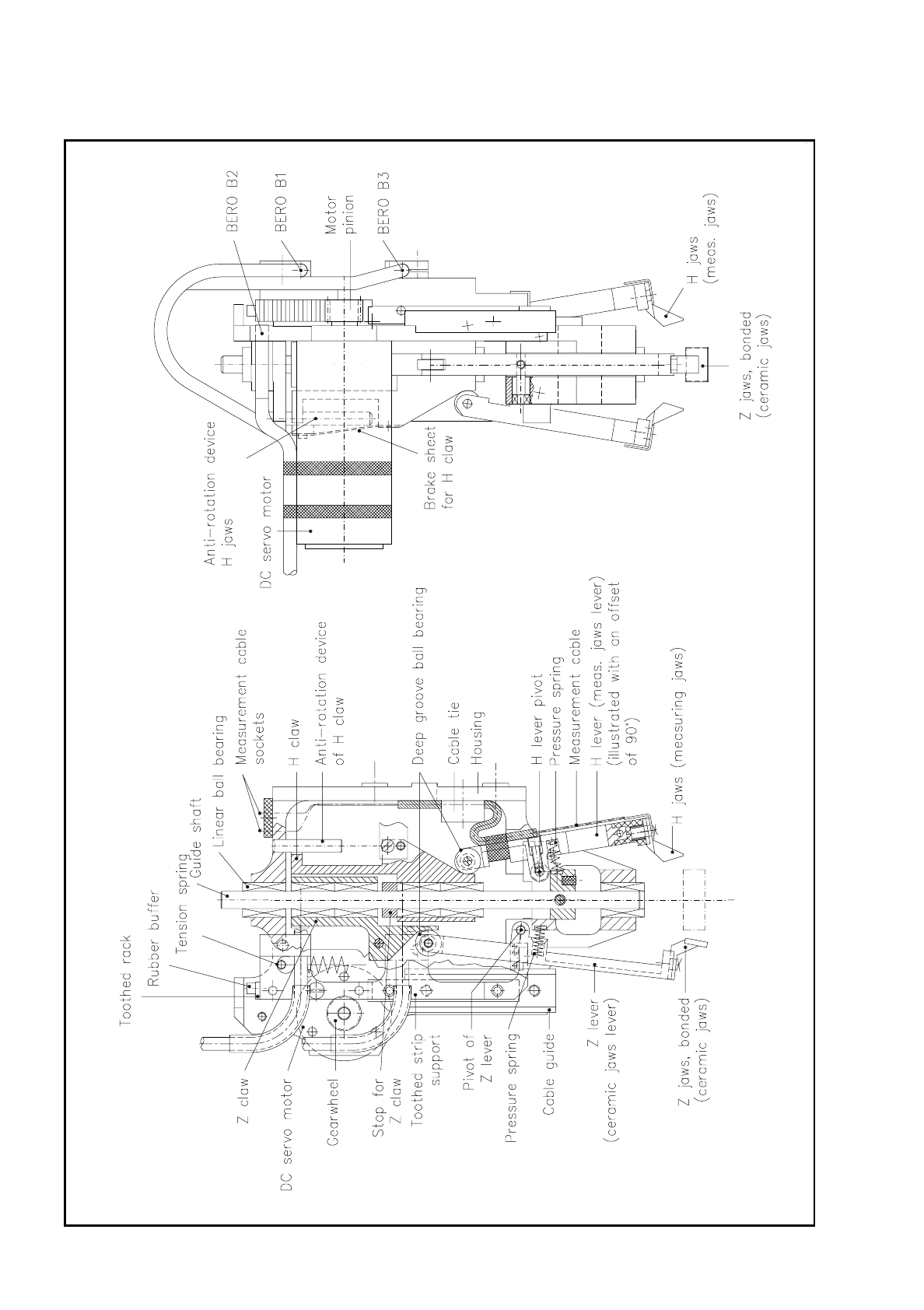
Fig. 9.7.4 Structure of the mechanical centering station (sectional diagram)
SIPLACE 80S/F/G Service Manual 9 Revolver Head
Edition 04/97
9 - 75
Fig. 9.7.5 Structure of the mechanical centering station (exploded view)
9 Revolver Head SIPLACE 80S/F/G Service Manual
Edition 04/97
9 - 76
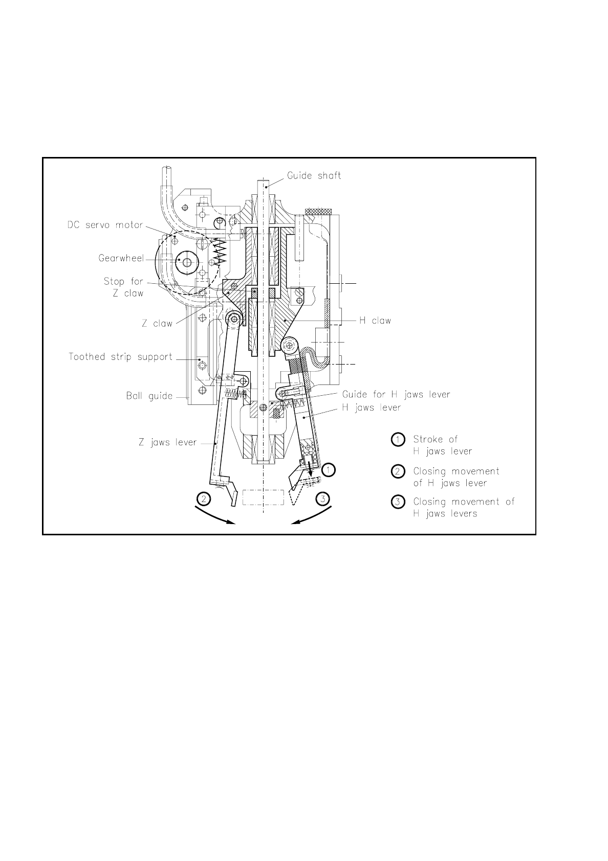
9.7.3 Sequence of Movements of the H and Z Jaws Levers
Please refer to the following diagram as you read the description of the sequence of movements in the
centering procedure.
Fig. 9.7.6 Sequence of movements of the h and z jaws levers
9.7.3.1 Sequence of Movements
1. The direct current servo motor moves the toothed rack and the toothed strip support towards the segment.
Here the h and z claws slide on the guide shaft towards the segment.
2. The deep-grooved ball bearings of the z jaws lever slide along the 45° incline of the z claw. The z jaws
close. At the same time the h jaws carry out a longitudinal movement until they are at the same height as
the z jaws.
3. The h and z claws move further on towards the segment. As soon as the z claw reaches the stop - that is,
the z jaws have closed to the defined separation - the closing movement of the h jaws lever begins.