80S-15贴片机.pdf - 第364页
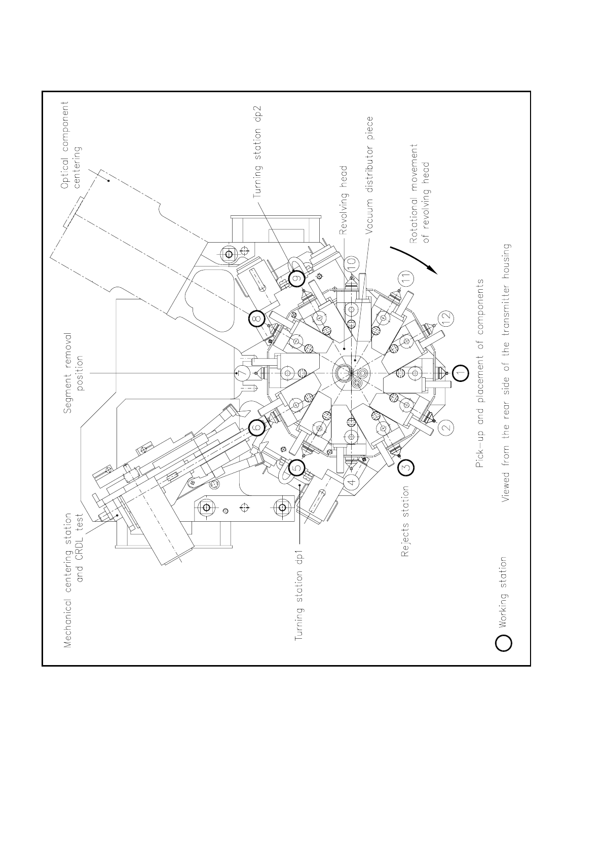
9 Revolver Head SIPLACE 80S/F/G Service Manual Edition 04/97 9 - 80 Fig. 9.8. 1 Segments - overview of the work stations
SIPLACE 80S/F/G Service Manual 9 Revolver Head
Edition 04/97
9 - 79
9.8 Segments
The revolver head has a total of 12 segments. The segments slide on the guide shafts of the revolver head.
Evacuation of the segment or nozzle takes place via the vacuum tube of the revolver head.
As the revolver head cycles on, the segments bring the picked-up components to the individual work stations
of the revolver head. At each work station the actions required for mounting the components will be
performed. The following revolver head stations are work stations:
At revolver head station 7 you can remove and fit segments using the segment removal tool.
Revolver head station Work performed
1 Pick-up and placement of components
3 Ejection of components
5
Turning station dp1 for rotating the components into the testing position with CRDL
testing
6
Mechanical centering station for centering and testing the electrical properties of the
components
8 Optical centering station for components
9 Turning station dp2 for rotating the components into the placement position
9 Revolver Head SIPLACE 80S/F/G Service Manual
Edition 04/97
9 - 80
Fig. 9.8.1 Segments - overview of the work stations
SIPLACE 80S/F/G Service Manual 9 Revolver Head
Edition 04/97
9 - 81
9.8.1 Segment Versions V1 and V2
At the present time you can use two different segment versions at the revolver head:
–
Segment version 1, designated E5.2 and
–
segment version 2, designated E6.1
NOTE
When performing servicing or routine maintenance work, make absolutely sure that you use only the spare
parts for the installed segment version. You must not use Version I spares with Version II segments, and vice
versa.
Differences between segment versions V1 and V2 (Fig. 9.8.2)
The above table shows the most important differences between Versions 1 and 2!
The modified nozzle seating in Version 2 means that so-called "long" nozzles can be used. With these
nozzles the placement shadow can be reduced and components as tall as 6 mm can be placed.
NOTE
This change in the design of the nozzle seating means that only nozzles for the version in question can be
used (in other words, nozzles are version-specific).
V1 V2
Label E5.2 E6.1
Cam Latching with leaf spring Ball latching
Nozzle seating suitable for long
nozzles
no yes
Light cover no yes