80S-15贴片机.pdf - 第375页
SIPLACE 80S/F/G Service Manual 9 Revolver Head Edition 04/97 9 - 91 9.10.2.1 Functional Description A segme nt of th e placem ent hea d picks up a co mponen t at rev olver h ead stati on 1. Th e revol ver hea d cycles on…
9 Revolver Head SIPLACE 80S/F/G Service Manual
Edition 04/97
9 - 90
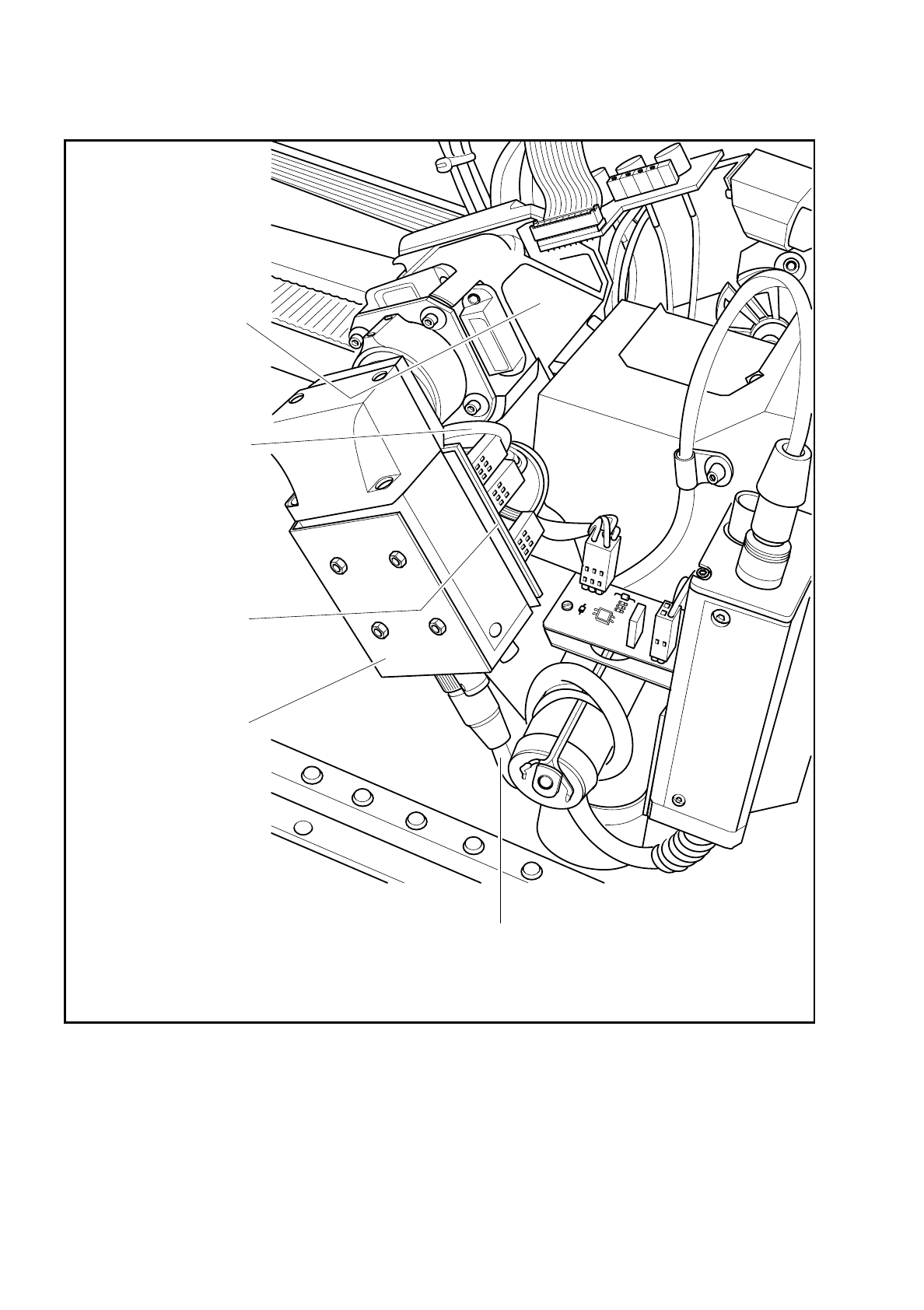
Fig. 9.10.1 Optical component centering (component vision system)
Optical component
centering unit with
illumination
Cable Y0575-W1
to conversion board
'small axis' Y0005
Y0059 board
Component illumination
control (older version
Y0028)
Camera amplifier
Sony XC75
Camera cable Y0574-W1 for power supply and signal lines
to conversion board 'small axis' Y0005

SIPLACE 80S/F/G Service Manual 9 Revolver Head
Edition 04/97
9 - 91
9.10.2.1 Functional Description
A segment of the placement head picks up a component at revolver head station 1. The revolver head cycles
on, further components are picked up. Revolver head station 8 accommodates the optical unit of the compo-
nent vision system. Upon arrival of the component, it is evenly illuminated with red light by staggered rows of
LEDs. The lens can reproduce with sharp focussing components up to 5 mm tall in the camera's CCD chip.
The digital image of the components created by the components camera is transmitted to the vision evalua-
tion unit. With the aid of digital image processing (the HALE technique) the evaluation unit compares the com-
ponent image with a synthetic model previously created in the GF editor (GF = package form). The
parameters so obtained provide information on positional deviations, angle of rotation, leads condition and
components re-identification. The HALE technique has proved to be very resistant to interference, such as
reflection and dazzle, different reflectivity of leads, dispersed light, and so on. It is quicker and more precise
than the matching technique. After successful measurement the segment rotates the component in revolver
head station 9 into the correct placement orientation. In revolver head station 1 the component is than
inserted onto the PCB with the correct orientation.

9 Revolver Head SIPLACE 80S/F/G Service Manual
Edition 04/97
9 - 92