80S-15贴片机.pdf - 第377页
SIPLACE 80S/F/G Service Manual 9 Revolver Head Edition 04/97 9 - 93 9.11 Option CRDL Testing If the opti on "CRDL testing" is instal led, the componen ts are che cked at th e mech anical centering s tation to e…

9 Revolver Head SIPLACE 80S/F/G Service Manual
Edition 04/97
9 - 92
SIPLACE 80S/F/G Service Manual 9 Revolver Head
Edition 04/97
9 - 93
9.11 Option CRDL Testing
If the option "CRDL testing" is installed, the components are checked at the mechanical centering station to
ensure that their electrical properties correspond to the specified values.
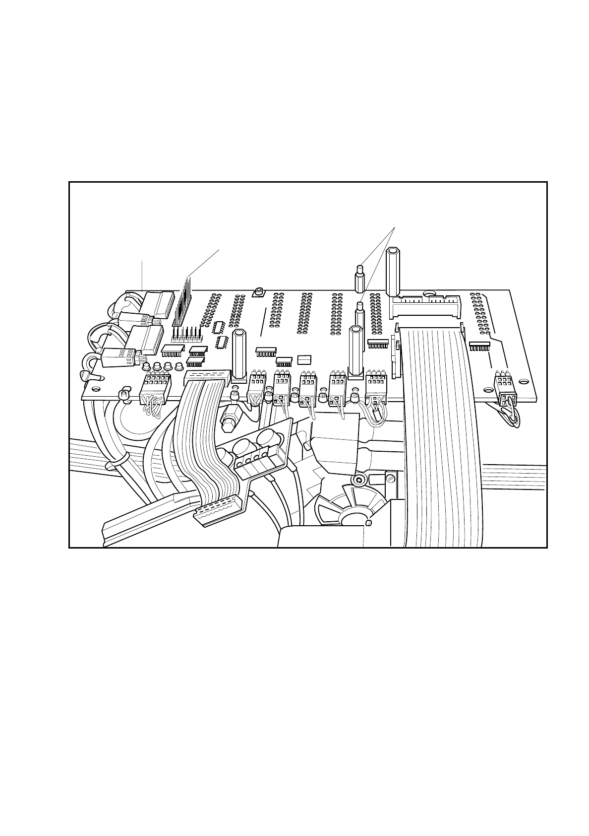
Fig. 9.11.1 CRDL testing board, connector on the conversion board “Small axis“ Y0005
Connector X1 for connection of
the CRDL testing board
Distance bolts with M3 threads
for fastening the CRDL testing board
Conversion board
'small axis' Y0005
9 Revolver Head SIPLACE 80S/F/G Service Manual
Edition 04/97
9 - 94
9.11.1 Electrical Connections
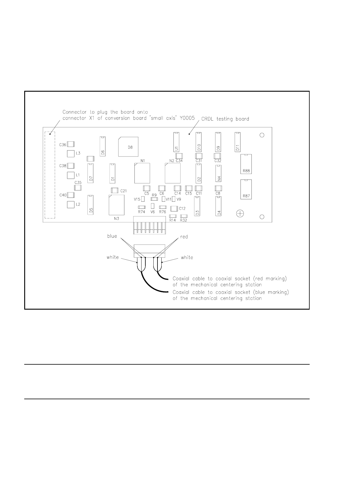
The CRDL testing board is plugged over plug X1 on the conversion board "Small axis" Y0005 and fastened
with two nuts M3 to the spacer pins.
Fig. 9.11.2 CRDL tester board
The testing board is connected via two coaxial electrical cables to the mechanical centering station. The
coaxial plugs are marked red and blue and must be plugged into the coaxial socket of the same color on the
mechanical centering station.
NOTE
Make sure that the coaxial plugs and sockets have the same color when plugged together otherwise there will
be mistakes in the polarity of the components to be inserted.
The mechanical centering station is already prepared for the CRDL testing option, as are the cable
connections from the conversion board "Small axis" Y0005 to the slide-in control unit.