80S-15贴片机.pdf - 第379页
SIPLACE 80S/F/G Service Manual 9 Revolver Head Edition 04/97 9 - 95 9.11.2 Measurement Ranges and Tolerances of the CRDL Tester The fol lowing tab les give an overvi ew of th e measur ement ran ges and to leranc es of th…
9 Revolver Head SIPLACE 80S/F/G Service Manual
Edition 04/97
9 - 94
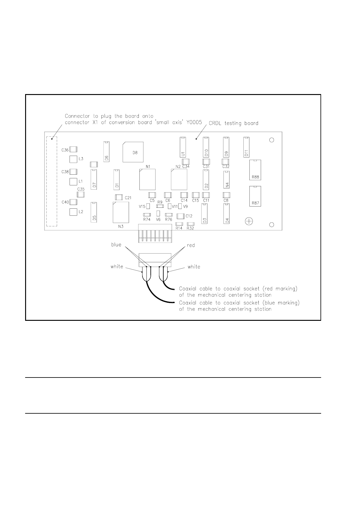
9.11.1 Electrical Connections
The CRDL testing board is plugged over plug X1 on the conversion board "Small axis" Y0005 and fastened
with two nuts M3 to the spacer pins.
Fig. 9.11.2 CRDL tester board
The testing board is connected via two coaxial electrical cables to the mechanical centering station. The
coaxial plugs are marked red and blue and must be plugged into the coaxial socket of the same color on the
mechanical centering station.
NOTE
Make sure that the coaxial plugs and sockets have the same color when plugged together otherwise there will
be mistakes in the polarity of the components to be inserted.
The mechanical centering station is already prepared for the CRDL testing option, as are the cable
connections from the conversion board "Small axis" Y0005 to the slide-in control unit.
SIPLACE 80S/F/G Service Manual 9 Revolver Head
Edition 04/97
9 - 95
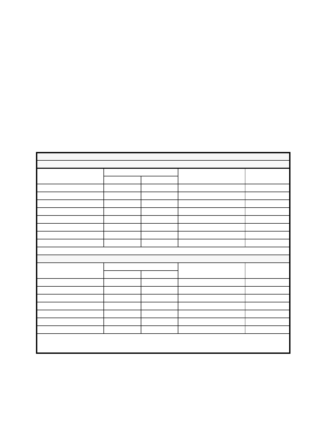
9.11.2 Measurement Ranges and Tolerances of the CRDL Tester
The following tables give an overview of the measurement ranges and tolerances of the CRDL tester.
9.11.2.1 CRDL Tester 80S
Comments on the tables
The information on precision is composed of two values.
–
The measurement tolerance in % of reading (o.r.)
–
An intrinsic error (Abs.) which affects every range of measurement.
For example, measured value 200 pF ± 3% tol.: ( ± ) 6 pF + ( ± ) 2pF o.r. =
± 8 pF measurement tolerance
CRDL Tester
C-testing
Range of measurement
Precision
Measurement voltage at 1.6
kHz
Comment
Tol. [%] o.r. Abs.
from 10 to 100 pF ± 3% ± 1 pF 5 V minimum 10 pF
from 100 pF to 1 nF ± 3% ± 2 pF 5 V
from 1 nF to 10 nF ± 3% ± 20 pF 0.5 V
from 10 nF to 100 nF ± 3% ± 100 pF 0.5 V
from 100 nF to 1
µ
F ± 4% ± 1 nF 0.5 V
from 1
µ
F to 1
0 µ
F ± 4% ± 20 nF 0.5 V
from 10
µ
F to 100
µ
F ± 5% ± 100 nF 0.5 V
from 100
µ
F to
2
20
µ
F ± 5% ± 200 nF 0.5 V maximum 220
µ
F
Polarity measurement of tantalum capacitors is not released
R-testing
Range of measurement
Precision
Measurement voltage at 1.6
kHz
Comment
Tol. [%] o.r. Abs.
10
Ω
to 100
Ω
± 3% ± 1
Ω
0.5 V minimum 10
Ω
100
Ω
to 1k
Ω
± 3% ± 2
Ω
0.5 V
1k
Ω
to 10k
Ω
± 3% ± 50
Ω
0.5 V
10k
Ω
to 100k
Ω
± 3% ± 200
Ω
0.5 V
100k
Ω
to 1M
Ω
± 3% ± 500
Ω
5 V
1M
Ω
to 10M
Ω
± 5% ± 20 k
Ω
5 V
10M
Ω
to 22M
Ω
± 10% ± 100 k
Ω
5 V maximum 22 M
Ω
In the range of measurement below 100
Ω
the possible contact resistance due to oxide film on the component or
deposits on the measuring jaws must be taken into account when tolerances are given.
(Up to 6
Ω
was measured during trials)
9 Revolver Head SIPLACE 80S/F/G Service Manual
Edition 04/97
9 - 96
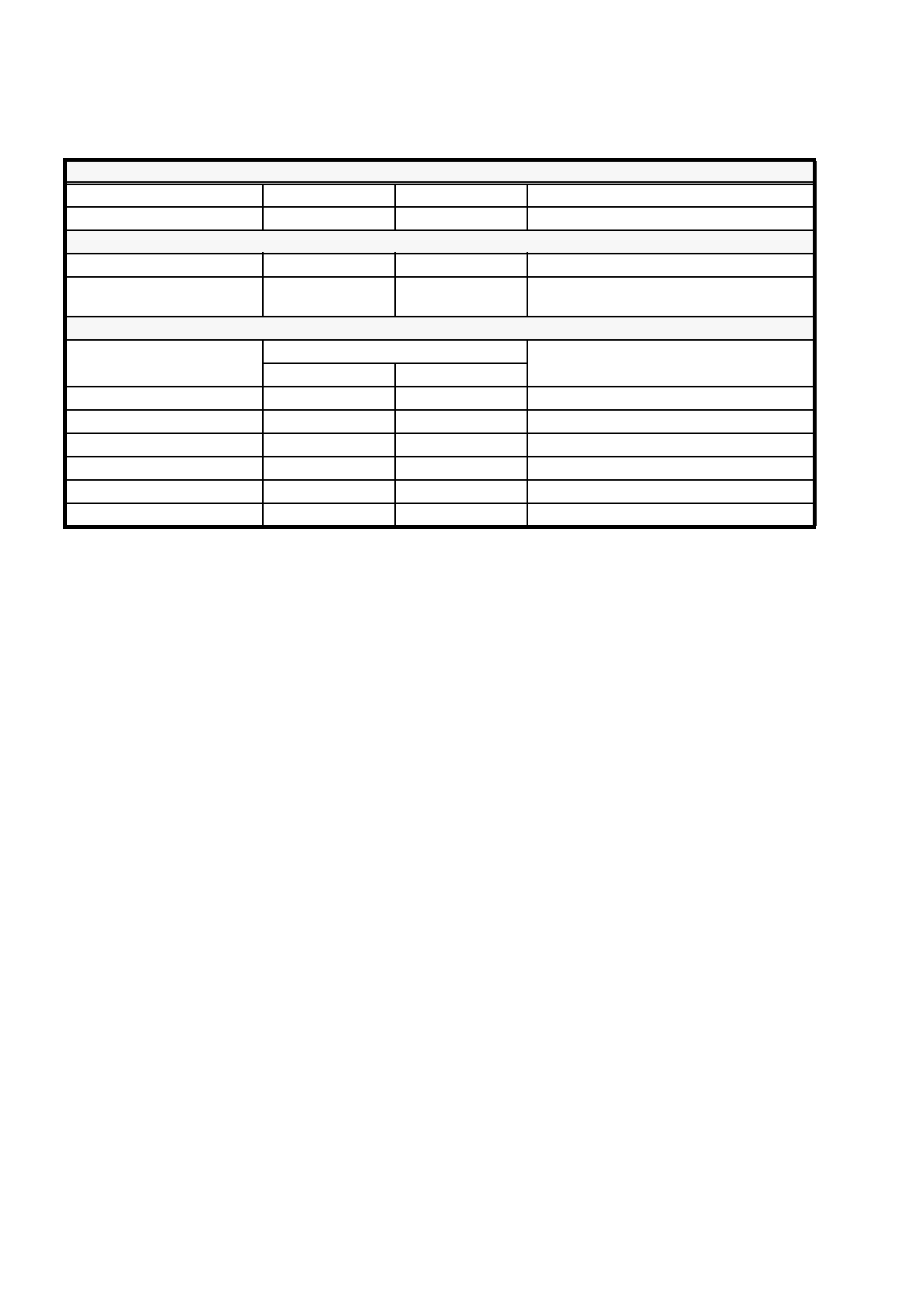
Diodes
Forward voltage Precision I Meas. Comment
± 10%0.1 to 5V 5mA ± 10% Reverse voltage must be larger than 23 V
Z Diodes
Zener voltage Precision I Meas. Comment
± 10% 5mA ± 10%
Forward voltage must be between 0.3 and
0.9 V
L Measurement
(with CRDL - EPROM Version 3.0)
Range of measurement
Precision
Measurement voltage at 1.6 kHz
Tol. [%] o.r. Abs.
1
µ
H to 10
µ
H ± 20% ± 0.5
µ
H0.5 V
10
µ
H to 100
µ
H ± 10% ± 1
µ
H0.5 V
100
µ
H to 1 mH ± 5% ± 5
µ
H0.5 V
1 mH to 10 mH ± 5% ± 100
µ
H0.5 V
10 mH to 100 mH ± 5% ± 200
µ
H0.5 V
100 mH to 820 mH ± 5% ± 500
µ
H0.5 V