80S-15贴片机.pdf - 第382页
9 Revolver Head SIPLACE 80S/F/G Service Manual Edition 04/97 9 - 98 Fig. 9.12. 1 Plug-in connections from the revolver head to conversion board Y0005 Key to Fig . 9.12.1 1 ’Sma ll axis ’ con versi on board Y0005 X1 Plug …

SIPLACE 80S/F/G Service Manual 9 Revolver Head
Edition 04/97
9 - 97
9.12 Dismantling the placement head
9.12.1 Tools and equipment
9.12.2 Spare parts
9.12.3 Dismantling the placement head
DANGER
OOO
Switch the placement machine off at the main switch and disconnect from the power supply.
WARNING
OO
Switch the compressed air supply off at the stop valve on the compressed air unit.
●
Remove all the segments using the appropriate segment changing device.
PLEASE NOTE:
Note the order of the segments and from which star position you removed the segments. In this way, you
will ensure that the configuration will be correct when you refit the segments.
From item number
Set of hexagon socket-head screwdrivers
SIPLACE segment changing device, version I 00310699-01
SIPLACE segment changing device, version II 00305987-02
Segment case 00302217-01
SITEST program
Adjustment instructions
Circuit diagrams
Cable ties
From item number
S-15 revolver head, booster-compatible 00320833S01
9 Revolver Head SIPLACE 80S/F/G Service Manual
Edition 04/97
9 - 98
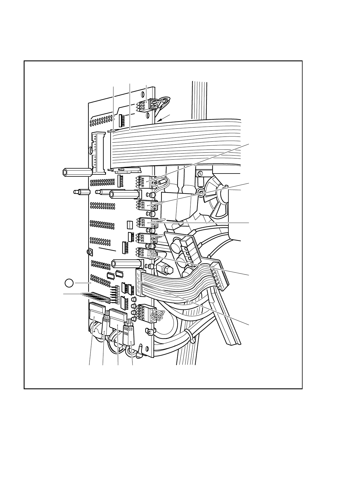
Fig. 9.12.1 Plug-in connections from the revolver head to conversion board Y0005
Key to Fig. 9.12.1
1 ’Small axis’ conversion board Y0005
X1 Plug for the CRDL measurement board (option)
X9 Ribbon cable to connector X1 on the revolver head
X10 Ribbon cable to connector X2 on the revolver head
X13 Ribbon cable to vacuum measurement board Y0007
X16
X17
X9
X10
X15X27
X20X18
X22
X23
X24
X25
X1
X13
1

SIPLACE 80S/F/G Service Manual 9 Revolver Head
Edition 04/97
9 - 99
●
Remove the cable ties and detach the following connectors
X9 X10 X13 X15 X17 X18
X22X20X23X24X25X27
from board Y0005 (see Fig. 9.12.1 on page 9 - 98)
PLEASE NOTE:
If a mechanical centering station is installed, detach the measuring cable from the CRDL measurement
board.
●
Detach the four compressed air lines from the vacuum generator block (see Fig. 9.12.2 on page 9 - 100)
●
Loosen the two hexagon socket-head screws for fixing the cover (point 1 in Fig. 9.12.3 on page 9 - 102)
and remove the cover.
●
Loosen the three M3 hexagon socket-head screws for fixing the revolver head to the gantry (see item 2 in
Fig. 9.12.3).
●
Carefully lift the placement head (see item 3 in Fig. 9.12.3) away from the parallel pins (see item 4 in Fig.
9.12.3) of the head support on the gantry (see item 5 in Fig. 9.13.1). Then remove the head from the place-
ment system.
X15 Cable - ’Motor/tacho/BERO z axis’
X16 Cable - ’z axis track’
X17 Cable - ’Screwdriver 2’
X18 Cable - ’Screwdriver 1’
X20 Cable - ’Forced air valve, placement circuit’
X21 Cable - ’Track signals, X axis’
X22 Cable - ’Illumination control, PCB camera’
X23 Cable - ’PCB camera’
X24 Cable - ’Illumination control, component camera’
X25 Cable - ’Component camera’
X26 Cable - ’BERO end position, X axis’
X27 Cable - ’Forced air valve, reject circuit’