80S-15贴片机.pdf - 第388页
9 Revolver Head SIPLACE 80S/F/G Service Manual Edition 04/97 9 - 104 PLEASE N OTE: If a mechan ical centeri ng station is i nstalled, rem ove the me asuring cabl e from the CRDL measu rement board. ● Loosen th e two hex …

SIPLACE 80S/F/G Service Manual 9 Revolver Head
Edition 04/97
9 - 103
9.13 Dismantling the encoder housing
9.13.1 Tools, equipment and consumables
9.13.2 Dismantling the encoder housing
DANGER
OOO
Switch the placement machine off at the main switch and disconnect from the power supply.
WARNING
OO
Switch the compressed air supply off at the stop valve on the compressed air unit.
●
Remove all the segments using the appropriate segment changing device and place the segments in the
segment case.
PLEASE NOTE:
Note the order of the segments and from which star position you removed the segments. In this way, you
will ensure that the configuration will be correct when you refit the segments.
or
●
Place the segment mount LTX over the individual segment guide shafts so that the segments cannot fall
off when the encoder housing is dismantled.
●
Remove the cable ties and detach the following plug-in connections
X9 X10 X22 X23 X24 and X25 X27
on board Y0005 (see Fig. 9.12.1 on page 9 - 98)
From item number
Set of hexagon socket-head screwdrivers
Diagonal cutter
SIPLACE segment changing device, version I 00310699-01
SIPLACE segment changing device, version II 00305897-02
Segment case 00302217-01
Segment mount LTX for the SIPLACE 80S-15/F3 revolver head 00306798-01
SITEST program
Adjustment instructions
Circuit diagrams
Cable ties

9 Revolver Head SIPLACE 80S/F/G Service Manual
Edition 04/97
9 - 104
PLEASE NOTE:
If a mechanical centering station is installed, remove the measuring cable from the CRDL measurement
board.
●
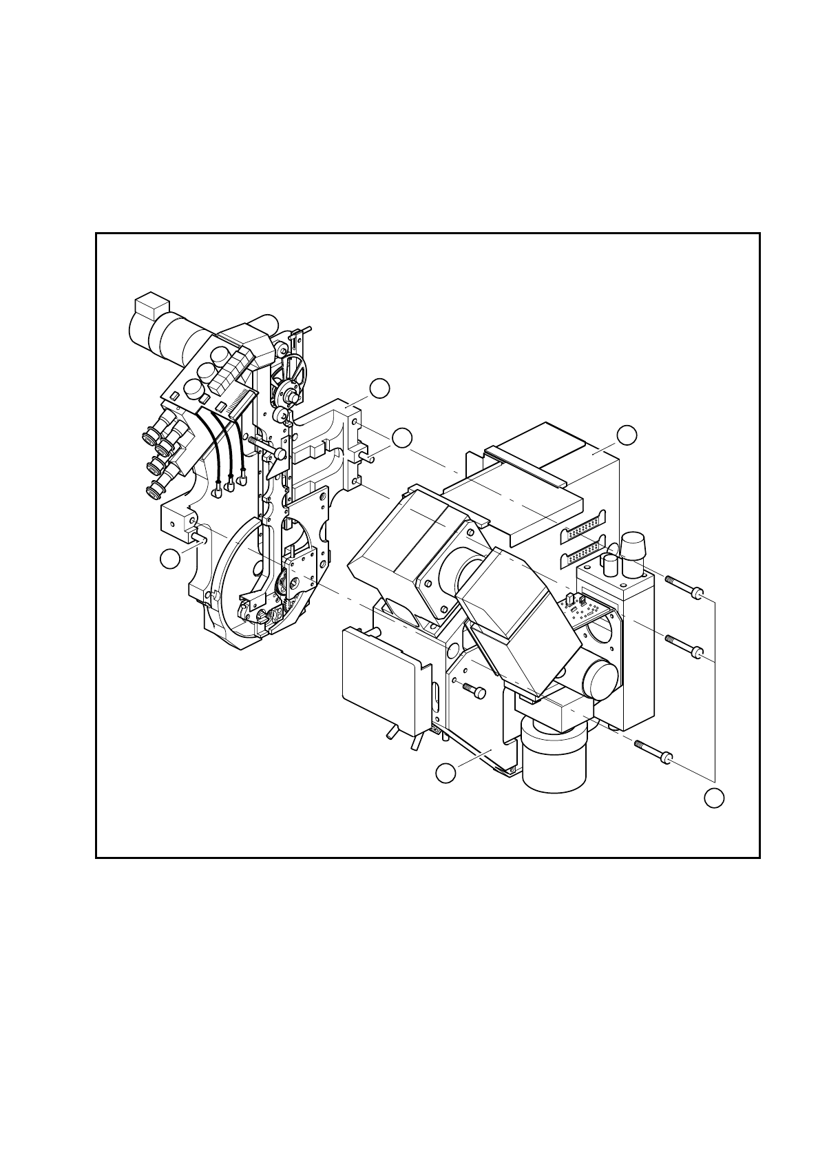
Loosen the two hexagon socket-head screws for fixing the covers (point 1 in Fig. 9.13.1) and remove the
cover.
●
Loosen the three M4 hexagon socket-head screws for fixing the encoder housing (point 3 in Fig. 9.13.1).
●
Carefully pull the encoder housing (point 3 in Fig. 9.13.1) off the parallel pins (point 5 in Fig. 9.13.1) on the
lifting carriage housing.
●
Take the encoder housing from the placement system and fix the encoder housing to the housing retainer.
9.13.3 Fitting the encoder housing
●
Reverse the above sequence to install.
CAUTION
O
• When fitting the encoder housing, ensure that the camera housing does not damage the components
on the vacuum measurement board.
• When fitting the encoder housing, ensure that the camera housing does not squash the vacuum hoses
leading to the vacuum measurement board.
PLEASE NOTE:
Note the coding on the plugs when you the reconnect the connectors on board Y0005.
CAUTION
O
Ensure that the cables are not damaged and that there is no strain on the clamped connections. Fix all the
cables with cables ties once more.
SIPLACE 80S/F/G Service Manual 9 Revolver Head
Edition 04/97
9 - 105
9.13.4 Adjustments
●
Carry out the adjustments in accordance with the adjustment instructions.
●
Calibrate the placement head using the SITEST program.
Fig. 9.13.1 Fitting the encoder housing to the lifting carriage housing
Key to Fig. 9.13.1
1 Cover 4 Lifting carriage housing
2 M4 fixing screws 5 Parallel pins
3 Encoder housing
1
3
4
5
5
2