80S-15贴片机.pdf - 第402页
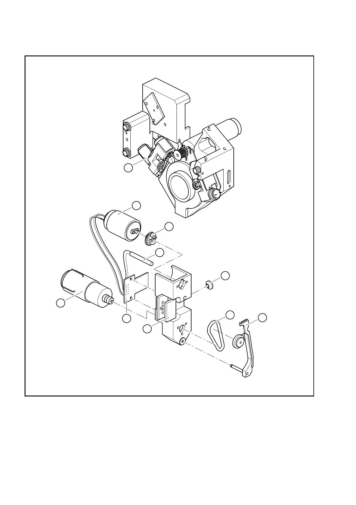
9 Revolver Head SIPLACE 80S/F/G Service Manual Edition 04/97 9 - 118 Fig. 9.16. 1 Structure of the turning station Key to F ig. 9.16.1 : see s ection 9 .16.2 ”Sp are part s”, page 117. 1 10 2 3 4 5 6 7 8 9

SIPLACE 80S/F/G Service Manual 9 Revolver Head
Edition 04/97
9 - 117
9.16 Service work on turning station dp1 and dp2
9.16.1 Tools, equipment and consumables
9.16.2 Spare parts
From item number
Set of screwdrivers
Hot air gun
Diagonal cutter
Soldering iron
0.15 mm feeler gauge
Ethyl alcohol
Unimoly GL82 lubricating grease
00313490-01
Cable ties
Number in
Fig. 9.16.1.
From item number
Rotary drive
1 00303925-04
Combined DC motor / tacho with driving wheel
2 00327482-01
DC motor, complete
3 00323190S01
Toothed wheel as shown in drawing
4 00300128-03
BERO 3RG 4603 2A B00/ 3.0 mm/SN=0.6mm/1S
5 00303945-01
BERO clamping disc
6 00315945-01
Toothed lever
7 00300127-04
Toothed lever and toothed wheel for rotary drive
7 + 4 00321472-01
O-ring 19 x 1.5 E70 B243E
8 00327165-01
Conversion board - ’Turn nozzle I’
9 00300015-01
Scanning unit for the dp axis / amplifier
10 00201455-01
9 Revolver Head SIPLACE 80S/F/G Service Manual
Edition 04/97
9 - 118
Fig. 9.16.1 Structure of the turning station
Key to Fig. 9.16.1: see section 9.16.2 ”Spare parts”, page 117.
1
10
2
3
4
5
6
7
8
9

SIPLACE 80S/F/G Service Manual 9 Revolver Head
Edition 04/97
9 - 119
9.16.3 Dismantling the turning station
●
Dismantle the encoder housing as described in Section 9.13.2 on page 9 - 103.
●
Dismantle the housing cover as described in Section 9.14 on page 9 - 107.
●
Loosen the two M2 nuts for fixing the amplifier board to the dp1 axis (see item 12 in Fig. 9.16.2) or dp2 axis
(see item 11 in Fig. 9.16.2).
●
Detach the connector of the dp1 amplifier board from slot X12 (see item 13 in Fig. 9.16.2) or the dp2 ampli-
fier board from slot X13 (see item 14 in Fig. 9.16.2).
●
Loosen the two M3 hexagon socket-head screws for fixing turning station dp1 (see item 1 in Fig. 9.16.2) or
dp2 (see item 3 in Fig. 9.16.2).
PLEASE NOTE:
To replace, remove the component camera from turning station dp2. This will ensure that the turning sta-
tion is seated correctly when reassembled.
●
Remove the turning station at the back of the encoder housing and carefully push the amplifier board
through the countersinking in the encoder housing.
PLEASE NOTE:
Be careful with the washers during dismantling. Some of them are made of plastic.