80S-15贴片机.pdf - 第403页
SIPLACE 80S/F/G Service Manual 9 Revolver Head Edition 04/97 9 - 119 9.16.3 Dismantling the turning station ● Dismantl e the e ncoder h ousing a s descri bed in Section 9 .13.2 on page 9 - 103. ● Dismantl e the h ousing …
9 Revolver Head SIPLACE 80S/F/G Service Manual
Edition 04/97
9 - 118
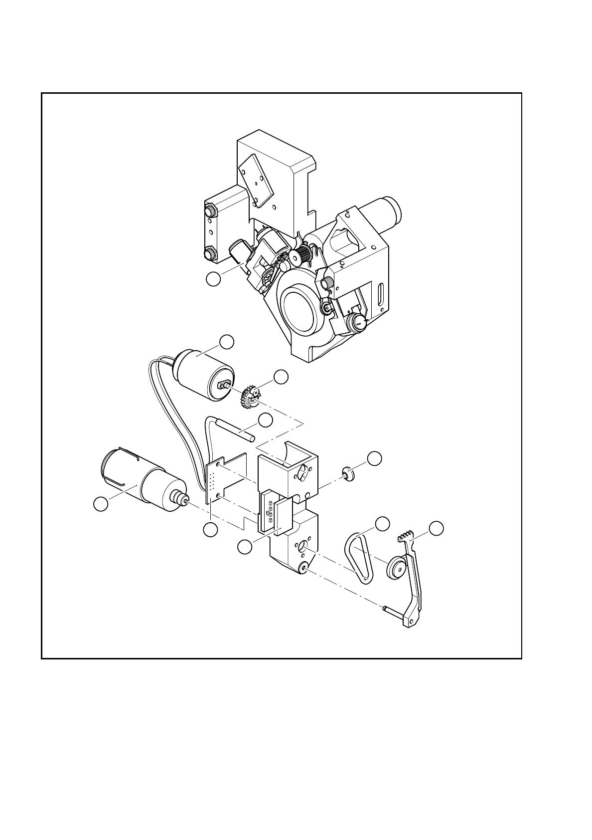
Fig. 9.16.1 Structure of the turning station
Key to Fig. 9.16.1: see section 9.16.2 ”Spare parts”, page 117.
1
10
2
3
4
5
6
7
8
9

SIPLACE 80S/F/G Service Manual 9 Revolver Head
Edition 04/97
9 - 119
9.16.3 Dismantling the turning station
●
Dismantle the encoder housing as described in Section 9.13.2 on page 9 - 103.
●
Dismantle the housing cover as described in Section 9.14 on page 9 - 107.
●
Loosen the two M2 nuts for fixing the amplifier board to the dp1 axis (see item 12 in Fig. 9.16.2) or dp2 axis
(see item 11 in Fig. 9.16.2).
●
Detach the connector of the dp1 amplifier board from slot X12 (see item 13 in Fig. 9.16.2) or the dp2 ampli-
fier board from slot X13 (see item 14 in Fig. 9.16.2).
●
Loosen the two M3 hexagon socket-head screws for fixing turning station dp1 (see item 1 in Fig. 9.16.2) or
dp2 (see item 3 in Fig. 9.16.2).
PLEASE NOTE:
To replace, remove the component camera from turning station dp2. This will ensure that the turning sta-
tion is seated correctly when reassembled.
●
Remove the turning station at the back of the encoder housing and carefully push the amplifier board
through the countersinking in the encoder housing.
PLEASE NOTE:
Be careful with the washers during dismantling. Some of them are made of plastic.
9 Revolver Head SIPLACE 80S/F/G Service Manual
Edition 04/97
9 - 120
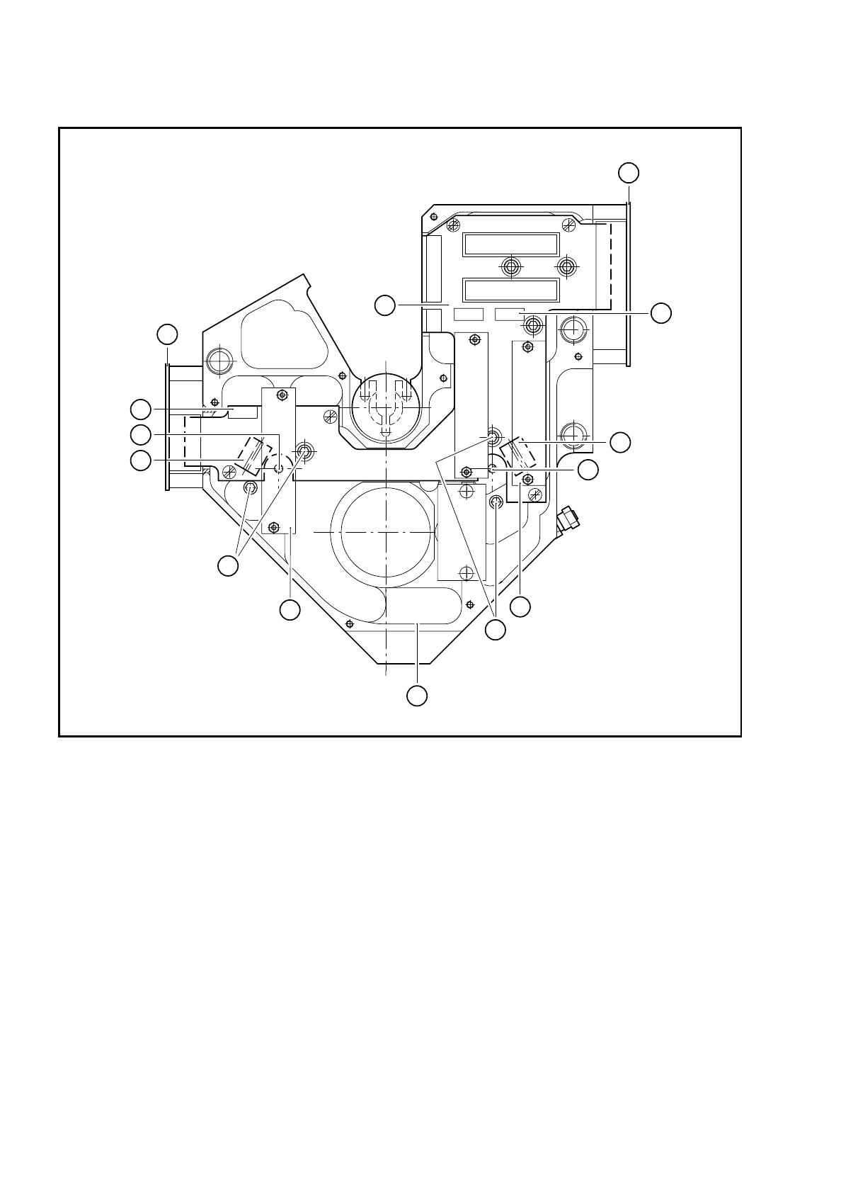
Fig. 9.16.2 Fixing screws for dp1 or dp2
Key to Fig. 9.16.2
1 2 x M3 hexagon socket-head screw for fixing dp1 10 M2x6 clamping screw for
2 Encoder housing - front view with housing cover removed BERO, dp2, hidden beneath
3 2 x M3 hexagon socket-head screw for fixing dp2 the amplifier board
4 ’Head’ conversion board Y0303 11 Amplifier, dp1 axis
5 Connector X8 for the ’Turn nozzle’ conversion board on dp1 12 Amplifier, dp2 axis
6 Connector X9 for the ’Turn nozzle’ conversion board on dp2 13 Slot X12 for plug
7 RSF 5x board for dp2 on amplifier board dp1
8 RSF 5x board for dp1 and star 14 Slot X12 for plug
9 M2x6 clamping screw for BERO, dp1 on amplifier board dp2
2
10 pol.
10 pol.
8 pol.
8 pol.
8 pol.
4 pol.
11 pol.
26 pol.
26 pol.
11
3
10
6
14
7
4
8
13
5
9
12
1