80S-15贴片机.pdf - 第404页
9 Revolver Head SIPLACE 80S/F/G Service M anual Edition 04/97 9 - 120 Fig. 9.16.2 Fixing screws for dp1 or dp2 Key to Fig . 9.16.2 1 2 x M3 hex agon soc ket-hea d screw for fixing dp1 10 M2x6 clamping s crew for 2 E ncod…

SIPLACE 80S/F/G Service Manual 9 Revolver Head
Edition 04/97
9 - 119
9.16.3 Dismantling the turning station
●
Dismantle the encoder housing as described in Section 9.13.2 on page 9 - 103.
●
Dismantle the housing cover as described in Section 9.14 on page 9 - 107.
●
Loosen the two M2 nuts for fixing the amplifier board to the dp1 axis (see item 12 in Fig. 9.16.2) or dp2 axis
(see item 11 in Fig. 9.16.2).
●
Detach the connector of the dp1 amplifier board from slot X12 (see item 13 in Fig. 9.16.2) or the dp2 ampli-
fier board from slot X13 (see item 14 in Fig. 9.16.2).
●
Loosen the two M3 hexagon socket-head screws for fixing turning station dp1 (see item 1 in Fig. 9.16.2) or
dp2 (see item 3 in Fig. 9.16.2).
PLEASE NOTE:
To replace, remove the component camera from turning station dp2. This will ensure that the turning sta-
tion is seated correctly when reassembled.
●
Remove the turning station at the back of the encoder housing and carefully push the amplifier board
through the countersinking in the encoder housing.
PLEASE NOTE:
Be careful with the washers during dismantling. Some of them are made of plastic.
9 Revolver Head SIPLACE 80S/F/G Service Manual
Edition 04/97
9 - 120
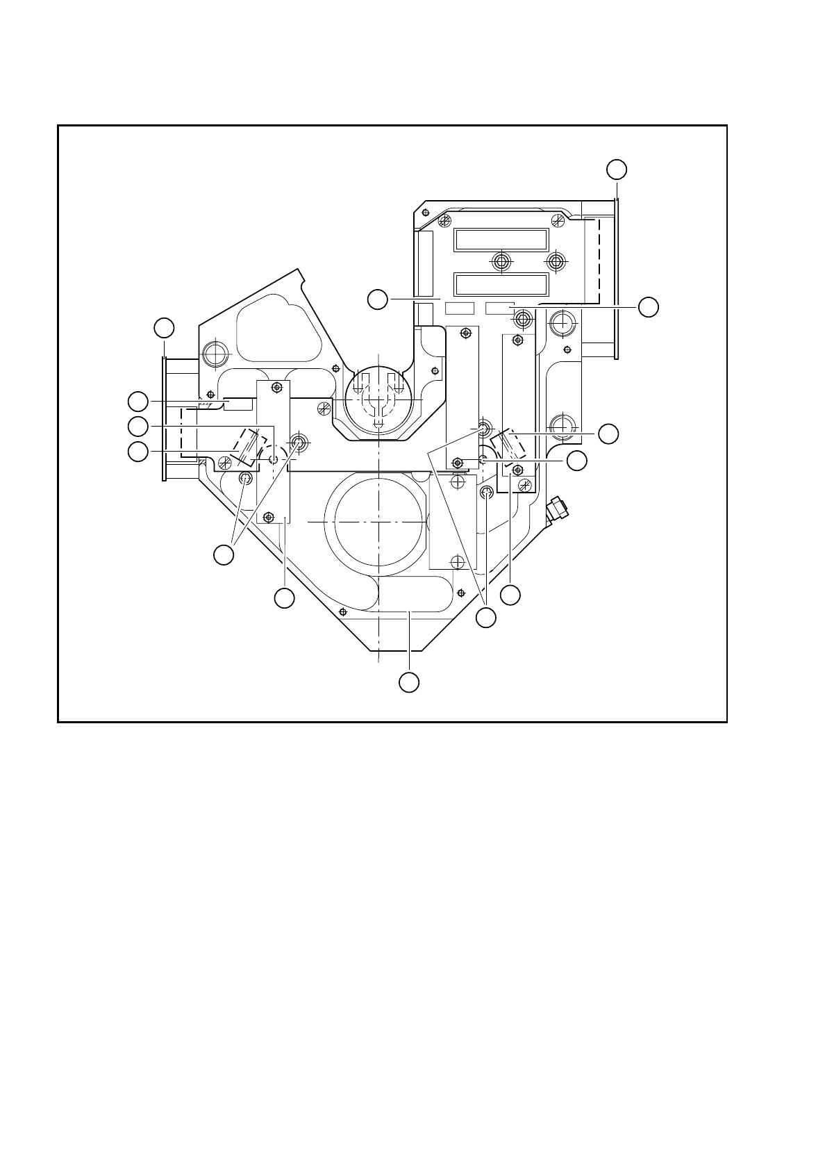
Fig. 9.16.2 Fixing screws for dp1 or dp2
Key to Fig. 9.16.2
1 2 x M3 hexagon socket-head screw for fixing dp1 10 M2x6 clamping screw for
2 Encoder housing - front view with housing cover removed BERO, dp2, hidden beneath
3 2 x M3 hexagon socket-head screw for fixing dp2 the amplifier board
4 ’Head’ conversion board Y0303 11 Amplifier, dp1 axis
5 Connector X8 for the ’Turn nozzle’ conversion board on dp1 12 Amplifier, dp2 axis
6 Connector X9 for the ’Turn nozzle’ conversion board on dp2 13 Slot X12 for plug
7 RSF 5x board for dp2 on amplifier board dp1
8 RSF 5x board for dp1 and star 14 Slot X12 for plug
9 M2x6 clamping screw for BERO, dp1 on amplifier board dp2
2
10 pol.
10 pol.
8 pol.
8 pol.
8 pol.
4 pol.
11 pol.
26 pol.
26 pol.
11
3
10
6
14
7
4
8
13
5
9
12
1

SIPLACE 80S/F/G Service Manual 9 Revolver Head
Edition 04/97
9 - 121
9.16.4 Installing the turning station
●
Clean the O-ring (see item 8 in Fig. 9.16.1) with ethyl alcohol.
●
Lightly grease the teeth of the toothed lever (see item 7 in Fig. 9.16.1) with Unimoly GL82.
●
Carefully push the amplifier board through the countersinking in the encoder housing.
●
Carefully insert the turning station. Be particularly careful to ensure that the connector contacts on the
’Turn nozzle’ conversion board (see item 9 in Fig. 9.16.1) are seated correctly in slot X8 or X9 on the
’Head’ conversion board Y0303 (see item 5 or 6 in Fig. 9.16.2).
CAUTION
O
You MUST ensure that the connector contacts on the ’Turn nozzle’ conversion board are aligned with the
contacts of connector X8 or X9. Otherwise there is a risk of short-circuit.
●
Connect the plug of the amplifier board to slot X12 or X13.
●
Fix the amplifier board in place.
●
Fix the turning station using the two hexagon socket-head screws.
●
Place a segment on the star and turn it towards the appropriate turning station.
●
Carefully pivot the turning station in towards the segment.
Ensure that the optical scanning unit of the turning station slides into the scale disk of the segment without
touching the disk.
●
Fit the housing cover and encoder housing as described in section 9.14, page 107 and 9.13, page 103.
9.16.5 Adjustments
●
Check the dynamic behavior of the dp1- or dp2 axis using the adjustment instructions.
●
Use the SITEST program to check that the station is functioning correctly.
9.16.6 Replacing the combined DC motor / tacho (drive motor)
●
Remove the drive O-ring (see item 2 in Fig. 9.16.3).
●
Mark the connecting wires of the motor and tacho (see item 1 in Fig. 9.16.3) and solder the wires.
●
Loosen the three M1.6 countersunk head screws for fixing the drive motor (see item 4 in Fig. 9.16.3).
●
Replace the drive motor and fix the new drive motor.
●
Pull new heat-shrink sleeves over the motor and tacho connecting wires.
●
Solder on the connecting wires and carefully shrink the heat-shrink sleeves.
●
Clean the drive O-ring with ethyl alcohol.
●
Pull on the drive O-ring. Be careful not to stretch it.
●
After assembly, check the dynamic behavior and functioning of the turning station with reference to the
adjustment instructions or using the SITEST program.