80S-15贴片机.pdf - 第407页
SIPLACE 80S/F/G Service Manual 9 Revolver Head Edition 04/97 9 - 123 9.16.8 Replacing the tooth ed lever and toothed wheel for the rotary drive PLEASE NOTE : The toot hed lever and to othed wheel are alwa ys cha nged tog…
9 Revolver Head SIPLACE 80S/F/G Service Manual
Edition 04/97
9 - 122
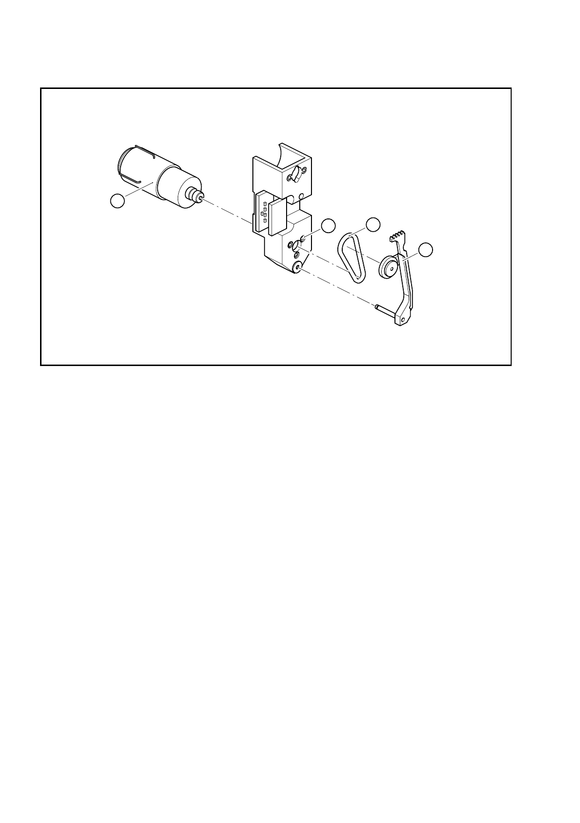
Fig. 9.16.3 Replacing the combined DC motor / tacho
Key to Fig. 9.16.3
9.16.7 Replacing the drive O-ring
Dynamic behavior problems with the drive can be caused by a loss of O-ring tension.
●
Replace the O-ring.
●
Clean the new O-ring with ethyl alcohol. Be careful not to stretch the O-ring when you fit it.
●
After installation, check the dynamic behavior and functioning of the turning station with reference to the
adjustment instructions or using the SITEST program.
1 Combined DC motor / tacho with driving wheel
2 O-ring
3 Toothed lever
4 3 M1.6x3 countersunk head screws
1
3
2
4
SIPLACE 80S/F/G Service Manual 9 Revolver Head
Edition 04/97
9 - 123
9.16.8 Replacing the toothed lever and toothed wheel for the rotary
drive
PLEASE NOTE:
The toothed lever and toothed wheel are always changed together.
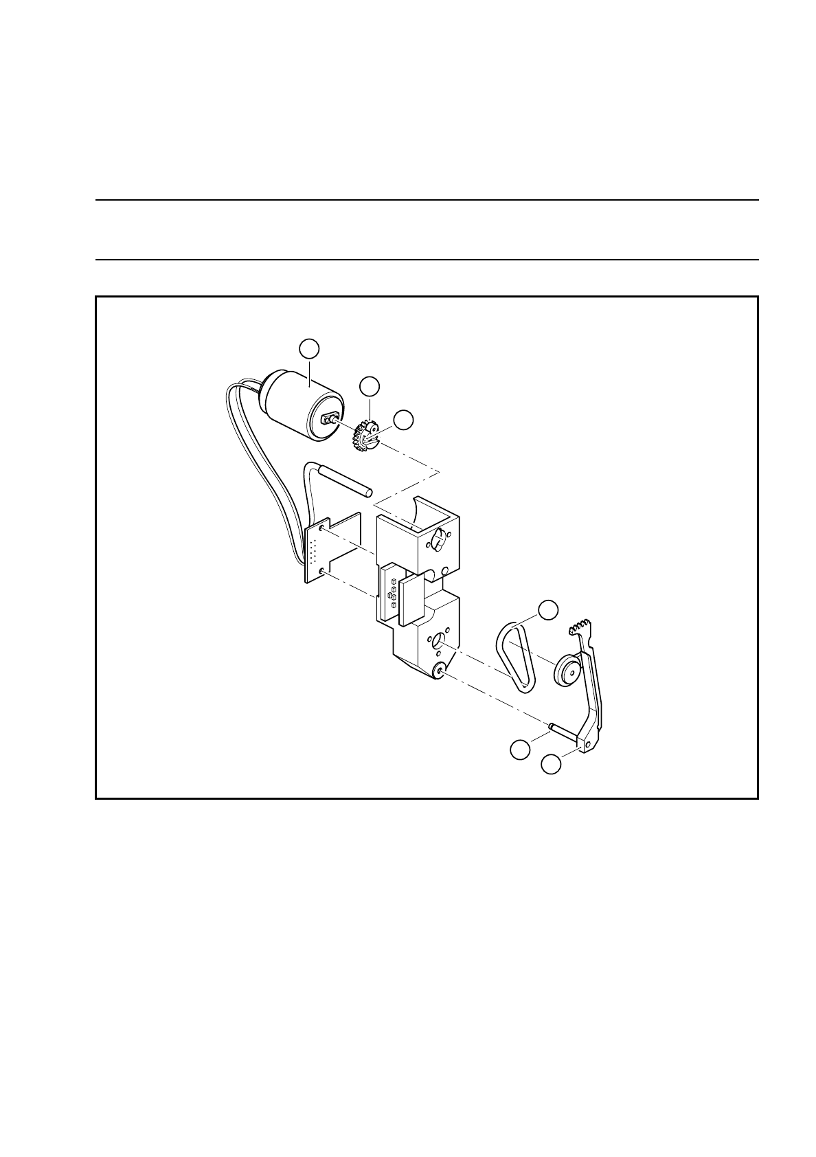
Fig. 9.16.4 Replacing the toothed lever and toothed wheel for the rotary drive
Key to Fig. 9.16.4
●
Remove the O-ring (see item 2 in Fig. 9.16.4).
●
Loosen the two M 1.4 fillister head screws (see item in Fig. 9.16.4) for fixing the toothed wheel (see item 4
in Fig. 9.16.4) on the feed motor (see item 5 in Fig. 9.16.4).
●
Remove the toothed wheel.
1 Toothed lever
2 O-ring
3 2 M1.4 x4 fillister head screws for fixing the toothed wheel
4 Toothed wheel
5 Feed motor
6 Retaining ring for the turning shaft of the toothed lever
5
3
1
2
6
4
9 Revolver Head SIPLACE 80S/F/G Service Manual
Edition 04/97
9 - 124
●
Remove the retaining ring (see item 6 in Fig. 9.16.4) from the turning shaft of the toothed lever (see item 1
in Fig. 9.16.4).
●
Pull the turning axis of the toothed lever out of the hole and the ball bearings.
●
Insert the new toothed lever and secure it with the retaining ring.
●
Fit the new toothed wheel.
●
Lightly grease the teeth of the toothed levers with Unimoly GL82.
●
Ensure that the O-ring is grease-free and pull it on. Be careful not to stretch the O-ring when you pull it on.
●
After assembly, check the dynamic behavior and functioning of the turning station with reference to the
adjustment instructions and using the SITEST program.
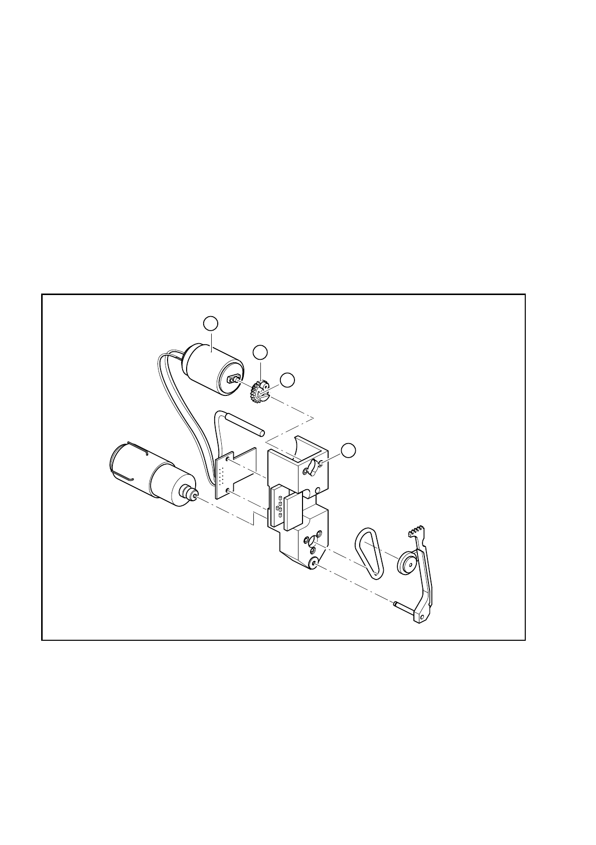
9.16.9 Replacing the complete DC motor (feed motor)
Fig. 9.16.5 Replacing the feed motor
Key to Fig. 9.16.5
●
Loosen the two M 1.4 fillister head screws (see item 2 in Fig. 9.16.5) for fixing the toothed wheel (see item
3 in Fig. 9.16.5).
●
Remove the toothed wheel.
1 2 M 1.6x3 countersunk head screws for fixing the
motor
3 Toothed wheel
2 2 M 1.4x4 fillister head screws for fixing the toothed
wheel
4 Feed motor
4
2
1
3