80S-15贴片机.pdf - 第413页
SIPLACE 80S/F/G Service Manual 9 Revolver Head Edition 04/97 9 - 129 9.17 Service wo rk o n the dR axis 9.17.1 Tools, equipmen t and consumables 9.17.2 Spare parts 9.17.3 Replacing the DC motor / tacho unit ● Dismantl e …
9 Revolver Head SIPLACE 80S/F/G Service Manual
Edition 04/97
9 - 128
●
Remove the turning station as shown in Section 9.16.3 on page 9 - 119.
●
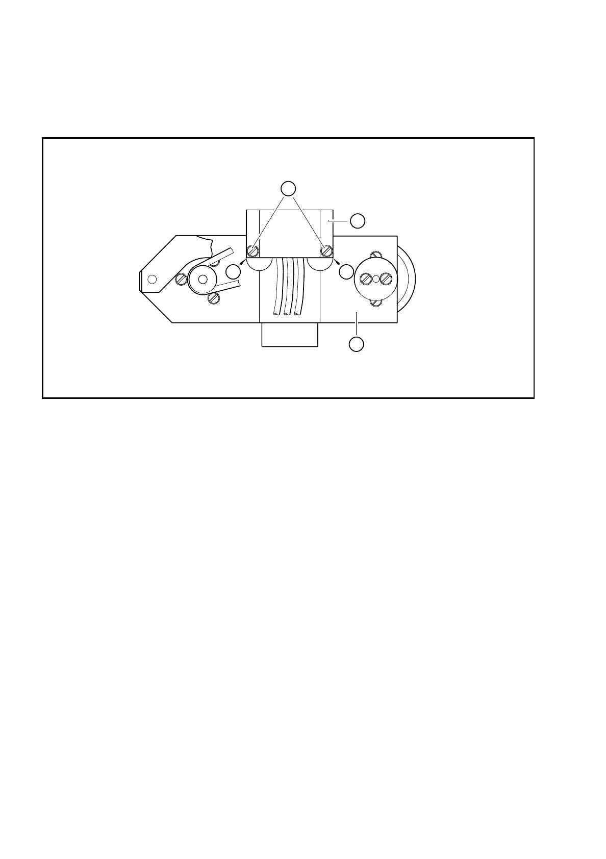
Loosen the two M 1.6x6 fillister head screws for fixing the scanning unit to the turning station (see item 2 in
Fig. 9.16.8).
Fig. 9.16.8 Scanning unit on the turning station
Key to Fig. 9.16.8
●
Remove the amplifier board and carefully pull the scanning unit through the countersinking in the encoder
housing.
●
Insert the new amplifier scanning unit.
●
Connect the plug on the amplifier board to connector X12 or X13.
●
Fix the amplifier board in place.
●
Fix the scanning unit to the turning station. Make sure that you mount the scanning unit on the stop as
shown in Fig. 9.16.8.
●
Install the turning station as shown in Section 9.16.4 on page 9 - 121.
●
After assembly, check the dynamic behavior and functioning of the turning station with reference to the
adjustment instructions and using the SITEST program.
1 Bottom of the turning station
2 M 1.6x6 fillister head screws
3 Scanning unit
A Scanning unit mounted on the stop
A
3
A
2
1

SIPLACE 80S/F/G Service Manual 9 Revolver Head
Edition 04/97
9 - 129
9.17 Service work on the dR axis
9.17.1 Tools, equipment and consumables
9.17.2 Spare parts
9.17.3 Replacing the DC motor / tacho unit
●
Dismantle the encoder housing as described in Section 9.13 on page 9 - 103.
●
Unplug the combined DC motor / tacho (see item 1 in Fig. 9.17.1) from slot X10 (see item 2 in Fig. 9.17.1)
on the ’Head’ conversion board Y0303.
●
Loosen the 3 M3x8 fillister head screws (see item 6 in Fig. 9.17.1) for fixing the motor.
●
Change the combined DC motor / tacho.
PLEASE NOTE:
Be careful not to stretch or damage the toothed belt.
●
Fix the combined DC motor / tacho in place
●
Check the toothed belt tension using the belt tension measuring device and the ’Measuring the belt ten-
sion’ user’s manual. If the toothed belt is tensioned correctly, the frequency should be 405 ± 35 Hz.
●
Plug the combined DC motor / tacho into slot X10.
From item number
Set of hexagon socket spanners
Set of screwdrivers
SIPLACE segment changing device, version I
00310699-01
SIPLACE segment changing device, version II
00305897-02
Segment case
00302217-01
Segment mount LTX for the SIPLACE 80S-15/F3 revolver head
00329262-01
Housing retainer
00306798-01
SITEST program
Adjustment instructions
Circuit diagrams
Belt belt tension measuring device, complete
00326015-01
Cable ties
From item number
DC motor / tacho unit with disk
00327787S01
Synchroflex 10 M2, 032/256 toothed belt
00303931S01
9 Revolver Head SIPLACE 80S/F/G Service Manual
Edition 04/97
9 - 130
●
After assembly, test the dynamic behavior and functioning of the dR axis drive with reference to the adjust-
ment instructions and using the SITEST program.
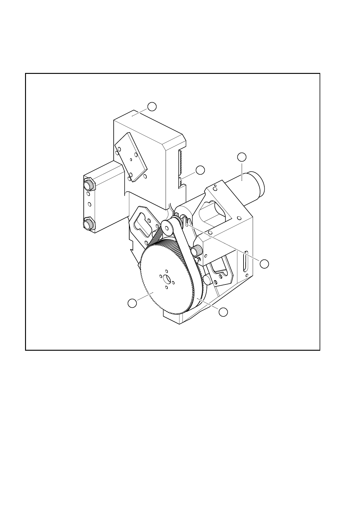
Fig. 9.17.1 DC motor / tacho unit for the dR axis
Key to Fig. 9.17.1
1 Combined DC motor / tacho, dR axis
2 Slot X10 for connecting the dR axis motor
3 Encoder housing
4 AL 14 M/112-0 synchronizing disk
5 Synchroflex 10 M2, 032/256 toothed belt
6 3 M3 x 8 fillister head screws
4
5
1
6
2
3