80S-15贴片机.pdf - 第424页
9 Revolver Head SIPLACE 80S/F/G Service Manual Edition 04/97 9 - 140 ● Insert th e new segm ent cl aw. ● Align th e screw driver bl ade wit h respect to toothed wheel 1 as show n in Fig . 9.12.2. ● Fix the s egment cl aw…
SIPLACE 80S/F/G Service Manual 9 Revolver Head
Edition 04/97
9 - 139
9.18.7 Replacing the segment claw
●
Loosen the M 1.6 x 4 fillister head screws on the cable bracket (see item 1 in Fig. 9.18.6).
●
Loosen the M 1.6 x 4 fillister head screws (see item 3 in Fig. 9.18.6) for clamping the BERO.
●
Pull the BERO out of the hole.
●
Loosen the two M 1.6 x 4 fillister head screws (see item 5 in Fig. 9.18.6) for fixing the segment claw.
●
Pull the segment claw carefully away from the parallel pins (see item 6 in Fig. 9.18.6).
●
Lightly grease the teeth of toothed wheel 1 (see item 4 in Fig. 9.18.5) with Unimoly GL82
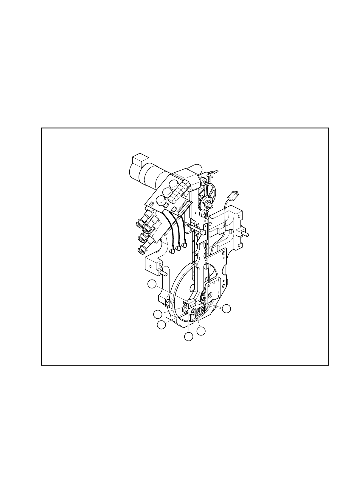
Fig. 9.18.6 Replacing the segment claw
Key to Fig. 9.18.6
1 Cable bracket
2BERO
3 M 1.6 x 4 fillister head screws for clamping the BERO
4 Segment claw
5 M 1.6 x 4 fillister head screws for fixing the segment claw
6 Parallel pin for positioning the segment claw
6
4
3
2
1
5

9 Revolver Head SIPLACE 80S/F/G Service Manual
Edition 04/97
9 - 140
●
Insert the new segment claw.
●
Align the screwdriver blade with respect to toothed wheel 1 as shown in Fig. 9.12.2.
●
Fix the segment claw.
●
Insert the BERO and set the operating distance of 0.2 mm as shown in Fig. 9.18.5.
●
Fix the cable bracket.
●
Ensure that the screwdriver blade is horizontal when you assemble the head. If it is not horizontal, the star
will not be able to turn the segments after assembly.
●
Check the functioning of screwdriver 1 with reference to the adjustment instructions and using the SITEST
program.

SIPLACE 80S/F/G Service Manual 9 Revolver Head
Edition 04/97
9 - 141
9.19 Service work on screwdriver 2
9.19.1 Tools, equipment and consumables
9.19.2 Spare parts
9.19.3 Screwdriver 2 - replacing the motor
●
Dismantle the encoder housing as described in Section 9.13 on page 9 - 103.
●
Loosen the two M 2.5 x 5 countersunk screws for fixing the link (see item 10 in Fig. 9.19.1).
●
Carefully remove the link from the parallel pins on the lifting carriage housing (see item 9 in Fig. 9.19.1).
●
Loosen the two countersunk head screws for fixing cover plate (see item 3a in Fig. 9.19.1) and stop (see
item 3 in Fig. 9.19.1).
●
Loosen the two M 1.4 x 5 fillister head screws on toothed wheel 1 (see item 2 in Fig. 9.19.1) and pull the
toothed wheel off the motor shaft.
●
Strip the heat-shrink sleeves from the electrical connections of the DC motor (see item 1 in Fig. 9.19.1) and
unsolder the cable.
From item number
Set of screwdrivers
Set of hexagon socket-head screwdrivers
Soldering iron
Hot air gun
Scribing iron
0.2 mm feeler gauge
Unimoly GL82 lubricating grease/ 25 g
00313490-01
Ethyl alcohol
Shrink-fit hose
Number in
Fig. 9.19.1.
From item number
DC motor, complete
1 00323190S01
Stop
3 00201268-06
Cover plate
3a 00320825-01
Toothed wheel 1 - reject
2 00318184-02
5 x 8 x 2.5 MF 85 ZZS miniature ball bearing
4 00303950S01
FS 8 x 10 spring washer
5 00201299-01
Toothed wheel 2 - reject
6 00318183S02
BERO 3RG4603-2AB00/3.0 MM/SN = 0.6 MM/1S
7 00303945-01
Toothed wheel holder
8 00201261-03