80S-15贴片机.pdf - 第431页
SIPLACE 80S/F/G Service Manual 9 Revolver Head Edition 04/97 9 - 147 9.19 .7 Replac ing the mi niat ure ba ll be aring , sprin g wash er an d to othed whee l 2 ’ reject’ Fig. 9.19.5 Replacing the miniature ball bearing, …
9 Revolver Head SIPLACE 80S/F/G Service Manual
Edition 04/97
9 - 146
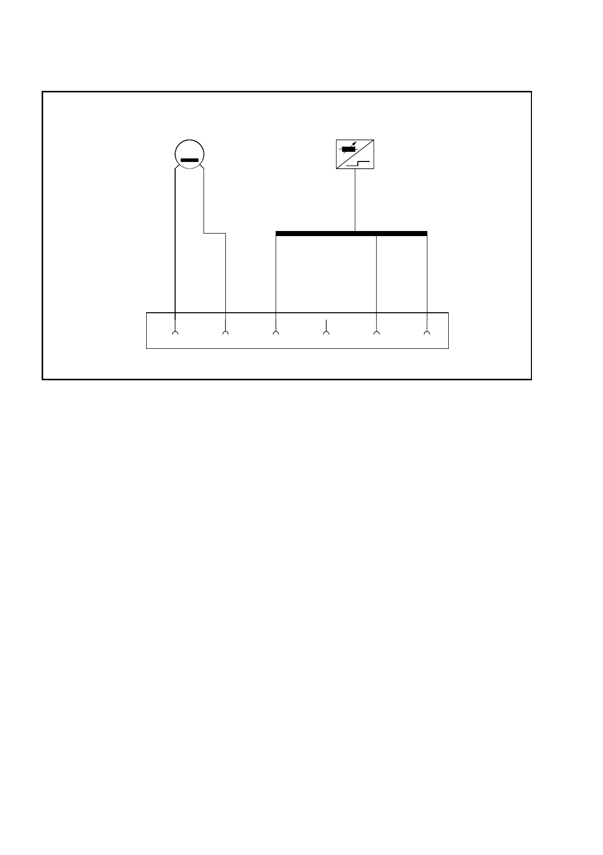
Fig. 9.19.4 Connecting the BERO to the plug
Key to Fig. 9.19.4
●
Set the operating distance to 0.2 mm as described for screwdriver 1 (see Fig. 9.18.5 on page 9 - 138 and
the text below).
●
Clamp the BERO in this position.
●
When assembling the head, make sure that you align the screwdriver blade (see item 4 in Fig. 9.19.2 on
page 9 - 143) with the 30° mark. If it is not aligned, the star will not be able to turn the segments after
assembly.
●
After assembly, check the functioning of the screwdriver with reference to the adjustment instructions and
using the SITEST program.
2 BERO cable: brown B1 BERO
3 BERO cable: blue X1 Plug for slot X17 on conversion board Y0005
6 BERO cable: black (see Fig. 9.12.1 on page 9 - 98)
M
+-
B1
X1
456123
SIPLACE 80S/F/G Service Manual 9 Revolver Head
Edition 04/97
9 - 147
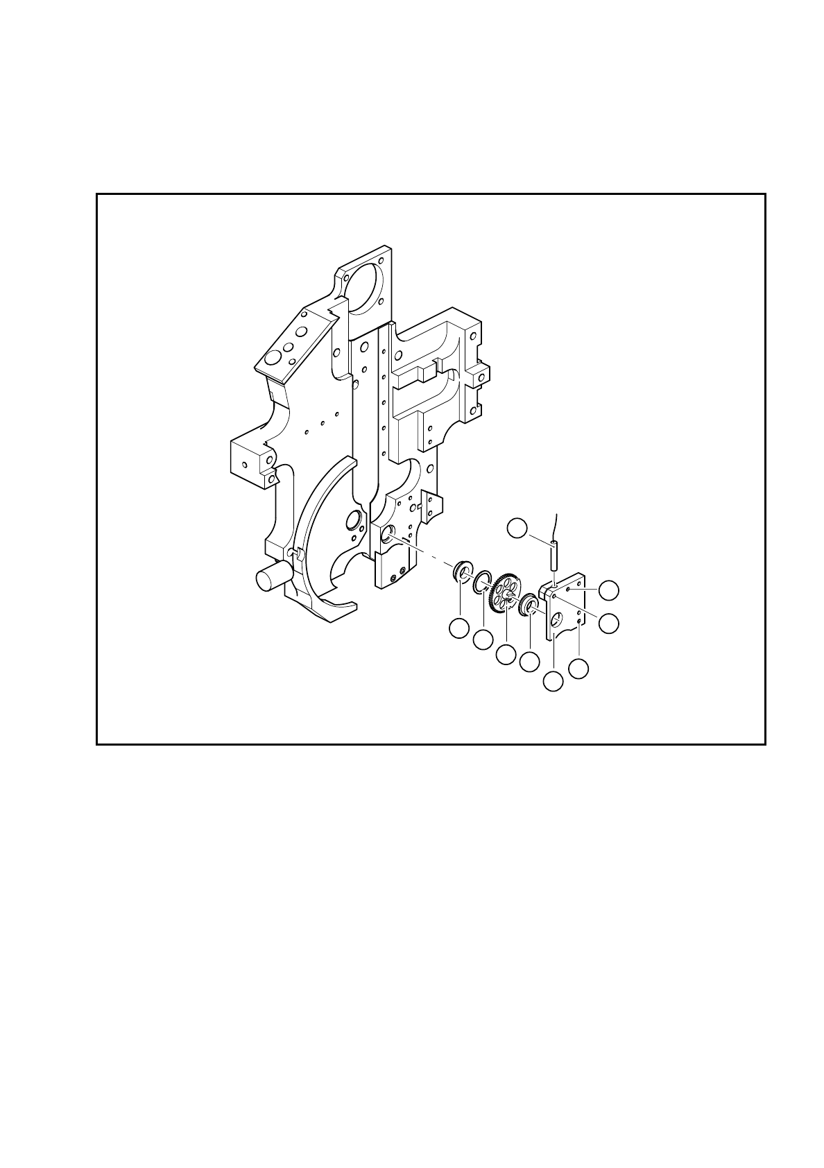
9.19.7 Replacing the miniature ball bearing, spring washer and toothed
wheel 2 ’reject’
Fig. 9.19.5 Replacing the miniature ball bearing, spring washer and toothed wheel 2 ’reject’
Key to Fig. 9.19.5
●
Loosen the M1.6x4 BERO clamping screw.
●
Pull the BERO out of the hole.
●
Loosen the two M2x6 fillister head screws (see item 7 in Fig. 9.19.5) for fixing the toothed wheel holder
(see item 5 in Fig. 9.19.5).
●
Carefully pull the toothed wheel holder away from the parallel pins.
●
Replace the miniature ball bearing, spring washer or toothed wheel 2.
●
Align the screwdriver blade with respect to toothed wheel 1 as shown in Fig. 9.19.2 on page 9 - 143.
●
Fix the toothed wheel holder in place.
1 5x8x2.5 MF85 ZZS miniature ball
bearing
5 Toothed wheel holder
2 Spring washer FS 8 x 10 6 M1.6x4 fillister head screw for clamping the BERO
3 Toothed wheel 2 - reject 7 M2x6 fillister head screw for fixing the toothed wheel
4BERO holder
4
5
1
1
2
3
6
7
7

9 Revolver Head SIPLACE 80S/F/G Service Manual
Edition 04/97
9 - 148
●
Insert the BERO and set the operating distance as described for the BERO of screwdriver 1 in Fig. 9.18.4
on page 9 - 137.
●
Make sure that you align the screwdriver blade with the 30° mark when you assemble the head. If it is not
aligned, the star will not be able to turn the segments after assembly.
●
After assembly, check the functioning of screwdriver 2 with reference to the adjustment instructions and
using the SITEST program.