80S-15贴片机.pdf - 第443页
SIPLACE 80S/F/G Service Manual 9 Revolver Head Edition 04/97 9 - 159 Fig. 9.22.2 Fixing s crews for the PCB camera Key to F ig. 9 .22.2 ● Loosen t he four M3 hexag on socket- head sc rews for fixing t he PCB camera to th…
9 Revolver Head SIPLACE 80S/F/G Service Manual
Edition 04/97
9 - 158
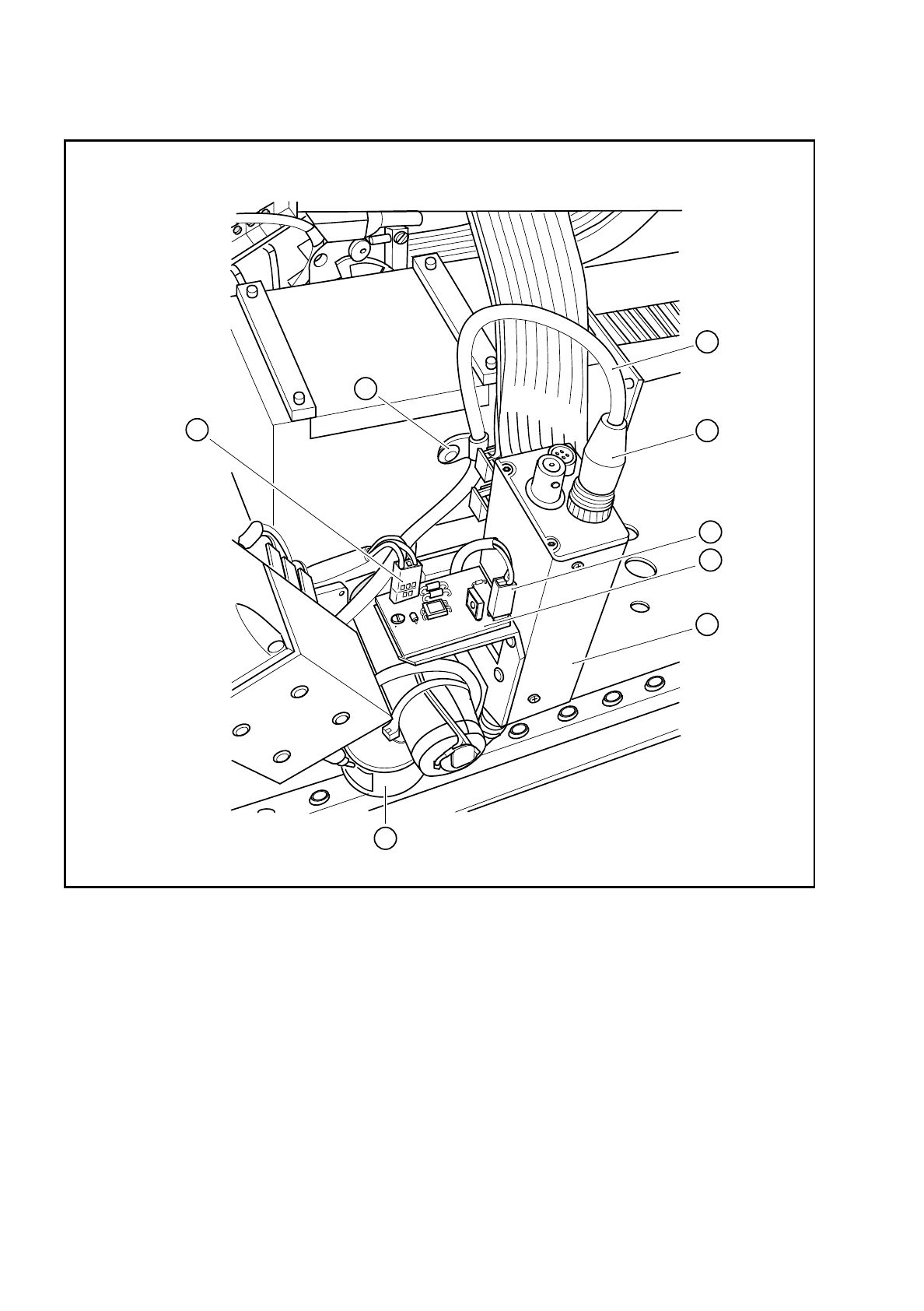
Fig. 9.22.1 Plug-in connections on the PCB camera
Key to Fig. 9.22.1
1 PCB camera amplifier 5 Connector X1 on cable Y0577
2 Connector X1 on the PCB camera cable
Y0597
6 Connector X2 on the cable for the lens system light-
ing
3 Cable clip for the PCB camera cable 7 Illumination control for the PCB camera Y0029
4 Cable: Pulnix camera - conversion board
Y0597
8 PCB optical system and PCB illumination
8
2
5
3
6
1
7
4
SIPLACE 80S/F/G Service Manual 9 Revolver Head
Edition 04/97
9 - 159
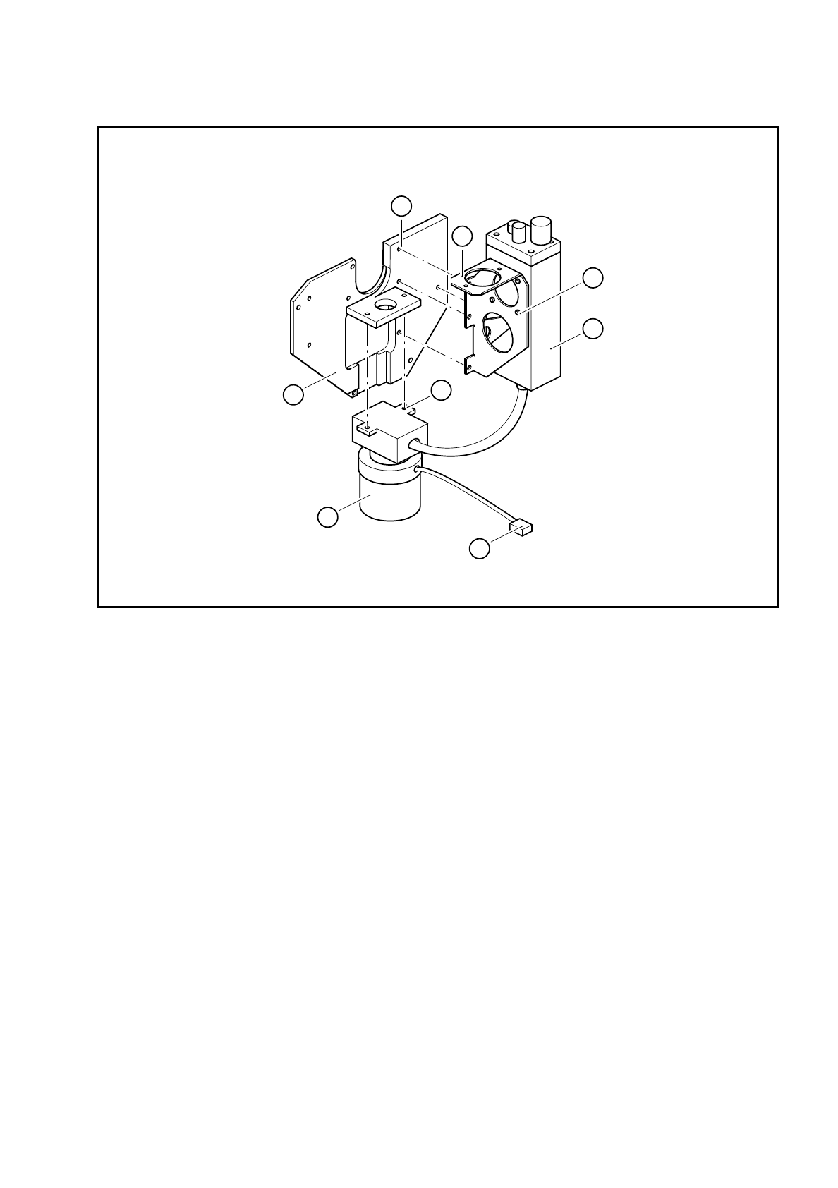
Fig. 9.22.2 Fixing screws for the PCB camera
Key to Fig. 9.22.2
●
Loosen the four M3 hexagon socket-head screws for fixing the PCB camera to the holder (see item 7 in
Fig. 9.22.2).
●
Loosen the two M3 fixing screws (see item 8 in Fig. 9.22.2) for the PCB optical system and remove the
PCB camera system.
9.22.4 Reassembling the PCB camera
●
Reverse the above sequence to reassemble.
●
Use the SITEST program to carry out all the calibration steps required, such as calibrating the PCB cam-
era, measuring the PCB /component offset, etc.
1 Housing cover 5 PCB camera holder
2 PCB optical system and PCB illumination 6 4 x M3x6 hexagon socket-head screws
3 Connector X2 on the PCB lens system cable 7 4 x M3x4 hexagon socket-head screws
4 PCB camera amplifier 8 2 x M3 hexagon socket-head screws
4
5
1
2
3
8
6
7

9 Revolver Head SIPLACE 80S/F/G Service Manual
Edition 04/97
9 - 160
9.22.5 Replacing the ’Pulnix camera - conversion board Y0597’ cable
DANGER
OOO
Switch the placement machine off at the main switch and disconnect from the power supply.
●
Remove connector X1 of PCB camera cable Y0597 (see item 2 in Fig. 9.22.1) from the PCB camera
amplifier.
●
Loosen the cable clip (see item 3 in Fig. 9.22.2).
●
Loosen the cable ties on conversion board Y0005 and disconnect the plug from slot X23 (see item X23 in
Fig. 9.12.1 on page 9 - 98).
●
Attach the new cable.
●
Carry out a function test using the SITEST program.
9.22.6 Replacing the ’PCB camera illumination control’ board
DANGER
OOO
Switch the placement machine off at the main switch and disconnect from the power supply.
●
Disconnect the two plugs from slots X1 and X2 on board Y0029 (see items 5, 6 and 7 in Fig. 9.22.1).
●
Replace the board.
●
Insert the plug
–
of cable Y0577 into slot X1 and
–
of the cable for the lens system lighting into slot X2.
●
Carry out a function test using the SITEST program.