80S-15贴片机.pdf - 第445页
SIPLACE 80S/F/G Service Manual 9 Revolver Head Edition 04/97 9 - 161 9.23 Servic e work o n the co mponent c amera 9.23.1 Tools, equipm ent and consum ables 9.23.2 Spare parts 9.23.3 Dismantling the compon ent camera DAN…

9 Revolver Head SIPLACE 80S/F/G Service Manual
Edition 04/97
9 - 160
9.22.5 Replacing the ’Pulnix camera - conversion board Y0597’ cable
DANGER
OOO
Switch the placement machine off at the main switch and disconnect from the power supply.
●
Remove connector X1 of PCB camera cable Y0597 (see item 2 in Fig. 9.22.1) from the PCB camera
amplifier.
●
Loosen the cable clip (see item 3 in Fig. 9.22.2).
●
Loosen the cable ties on conversion board Y0005 and disconnect the plug from slot X23 (see item X23 in
Fig. 9.12.1 on page 9 - 98).
●
Attach the new cable.
●
Carry out a function test using the SITEST program.
9.22.6 Replacing the ’PCB camera illumination control’ board
DANGER
OOO
Switch the placement machine off at the main switch and disconnect from the power supply.
●
Disconnect the two plugs from slots X1 and X2 on board Y0029 (see items 5, 6 and 7 in Fig. 9.22.1).
●
Replace the board.
●
Insert the plug
–
of cable Y0577 into slot X1 and
–
of the cable for the lens system lighting into slot X2.
●
Carry out a function test using the SITEST program.

SIPLACE 80S/F/G Service Manual 9 Revolver Head
Edition 04/97
9 - 161
9.23 Service work on the component camera
9.23.1 Tools, equipment and consumables
9.23.2 Spare parts
9.23.3 Dismantling the component camera
DANGER
OOO
Switch the placement machine off at the main switch and disconnect from the power supply.
●
Remove connector X2 (see item 2 in Fig. 9.23.1) from the component camera.
●
Remove connector X1 (see item 3 in Fig. 9.23.1) from slot X3 on illumination control board Y0059.
From item number
Set of hexagon socket-head screwdrivers
Diagonal cutter
Cable ties
SITEST program
From item number
Vision system module, assembly
00309751S02
9 Revolver Head SIPLACE 80S/F/G Service Manual
Edition 04/97
9 - 162
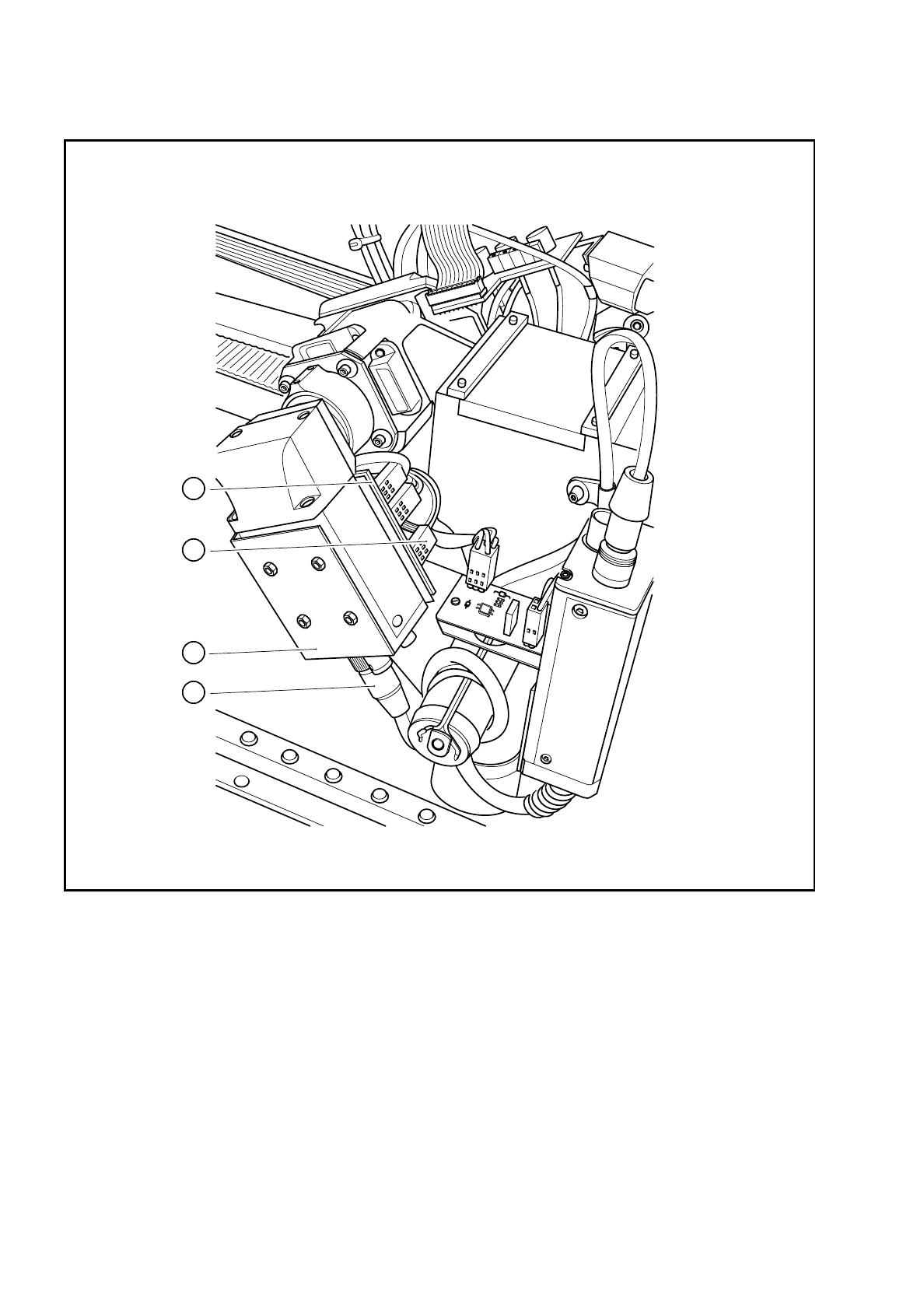
Fig. 9.23.1 Electrical connections on the component camera
Key to Fig. 9.23.1
1 Component camera system 3 Connector X1 on the control cable for the compo-
nent vision system Y0593
2 Connector X2 on the camera cable for the com-
ponent vision system Y0574
4 ’Illumination control for the
component camera’ board Y0059
1
2
3
4