80S-15贴片机.pdf - 第447页
SIPLACE 80S/F/G Service Manual 9 Revolver Head Edition 04/97 9 - 163 Fig. 9.23.2 Fixing the component camera to the revolver head Key to F ig. 9 .23.2 ● Carefully lift out th e camera. ● Before reinsta lling the ca mera,…
9 Revolver Head SIPLACE 80S/F/G Service Manual
Edition 04/97
9 - 162
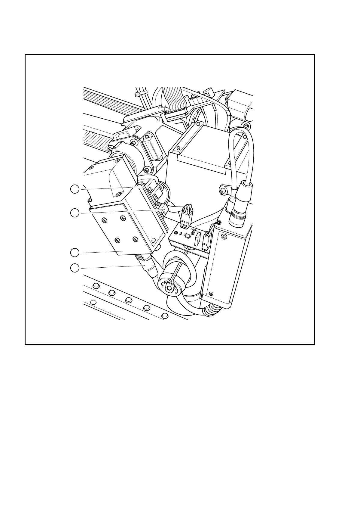
Fig. 9.23.1 Electrical connections on the component camera
Key to Fig. 9.23.1
1 Component camera system 3 Connector X1 on the control cable for the compo-
nent vision system Y0593
2 Connector X2 on the camera cable for the com-
ponent vision system Y0574
4 ’Illumination control for the
component camera’ board Y0059
1
2
3
4
SIPLACE 80S/F/G Service Manual 9 Revolver Head
Edition 04/97
9 - 163
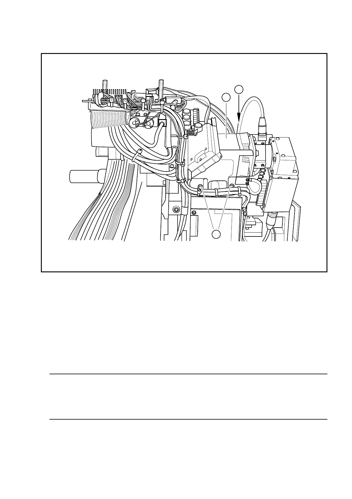
Fig. 9.23.2 Fixing the component camera to the revolver head
Key to Fig. 9.23.2
●
Carefully lift out the camera.
●
Before reinstalling the camera, check that the contact surfaces on the revolver head and camera are
clean.
●
Carefully insert the camera. In particular, make sure that the parallel pins slide fully into the holes. The
camera must lie flat on the contact surface of the revolver head.
WARNING
O
First insert the fixing screws. Do not tighten the screws until the camera and revolver head contact sur-
faces lie flat against one another. If they are not flat, the camera housing may tilt, resulting in damage to
the revolver head. The entire revolver head will then have to be replaced.
●
Use the SITEST program to carry out all the calibration steps required, such as calibrating the component
camera, measuring the PCB /component offset, etc.
❒
1 Component camera system for the revolver head
2 3 M4 x 10 hexagon socket-head screws for fixing the camera module to the revolver head
2
2
1

9 Revolver Head SIPLACE 80S/F/G Service Manual
Edition 04/97
9 - 164