80S-15贴片机.pdf - 第448页
9 Revolver Head SIPLACE 80S/F/G Service Manual Edition 04/97 9 - 164
SIPLACE 80S/F/G Service Manual 9 Revolver Head
Edition 04/97
9 - 163
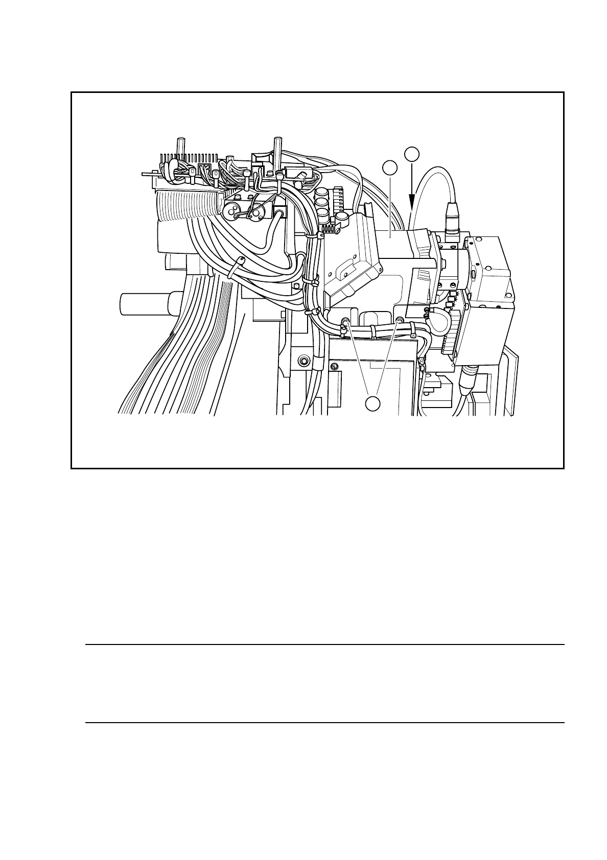
Fig. 9.23.2 Fixing the component camera to the revolver head
Key to Fig. 9.23.2
●
Carefully lift out the camera.
●
Before reinstalling the camera, check that the contact surfaces on the revolver head and camera are
clean.
●
Carefully insert the camera. In particular, make sure that the parallel pins slide fully into the holes. The
camera must lie flat on the contact surface of the revolver head.
WARNING
O
First insert the fixing screws. Do not tighten the screws until the camera and revolver head contact sur-
faces lie flat against one another. If they are not flat, the camera housing may tilt, resulting in damage to
the revolver head. The entire revolver head will then have to be replaced.
●
Use the SITEST program to carry out all the calibration steps required, such as calibrating the component
camera, measuring the PCB /component offset, etc.
❒
1 Component camera system for the revolver head
2 3 M4 x 10 hexagon socket-head screws for fixing the camera module to the revolver head
2
2
1

9 Revolver Head SIPLACE 80S/F/G Service Manual
Edition 04/97
9 - 164

SIPLACE 80S/80F/G Service Manual 10 Siplace G automatic glue applicator
Edition 06/98
10 - I
Contents
Page
10 Siplace G automatic glue applicator
10.1 Faults on the glue application head . . . . . . . . . . . . . . . . . . . . . . . . . . . . . . . . . . . . . . . . . 10 - 3
10.1.1 Possible causes of errors. . . . . . . . . . . . . . . . . . . . . . . . . . . . . . . . . . . . . . . . . . . . . . . . . . .10 - 3
10.2 Replacement work on the glue application head G . . . . . . . . . . . . . . . . . . . . . . . . . . . . 10 - 7
10.2.1 Safety instructions . . . . . . . . . . . . . . . . . . . . . . . . . . . . . . . . . . . . . . . . . . . . . . . . . . . . . . . .10 - 7
10.2.2 Overview. . . . . . . . . . . . . . . . . . . . . . . . . . . . . . . . . . . . . . . . . . . . . . . . . . . . . . . . . . . . . . . . 10 - 7
10.2.2.1 Tools required. . . . . . . . . . . . . . . . . . . . . . . . . . . . . . . . . . . . . . . . . . . . . . . . . . . . . . . . . . . . 10 - 8
10.2.2.2 Preparatory tasks . . . . . . . . . . . . . . . . . . . . . . . . . . . . . . . . . . . . . . . . . . . . . . . . . . . . . . . . . 10 - 8
10.2.3 Replacing the glue application head. . . . . . . . . . . . . . . . . . . . . . . . . . . . . . . . . . . . . . . . . . .10 - 8
10.2.3.1 Removal . . . . . . . . . . . . . . . . . . . . . . . . . . . . . . . . . . . . . . . . . . . . . . . . . . . . . . . . . . . . . . . . 10 - 9
10.2.3.2 Installation . . . . . . . . . . . . . . . . . . . . . . . . . . . . . . . . . . . . . . . . . . . . . . . . . . . . . . . . . . . . . 10 - 10
10.2.4 Replacing the Z axis motor. . . . . . . . . . . . . . . . . . . . . . . . . . . . . . . . . . . . . . . . . . . . . . . . .10 - 12
10.2.4.1 Removal . . . . . . . . . . . . . . . . . . . . . . . . . . . . . . . . . . . . . . . . . . . . . . . . . . . . . . . . . . . . . . . 10 - 13
10.2.4.2 Installation . . . . . . . . . . . . . . . . . . . . . . . . . . . . . . . . . . . . . . . . . . . . . . . . . . . . . . . . . . . . . 10 - 13
10.2.5 Replacing the X2/Y2 axis direct-drive motor . . . . . . . . . . . . . . . . . . . . . . . . . . . . . . . . . . .10 - 15
10.2.5.1 Removal . . . . . . . . . . . . . . . . . . . . . . . . . . . . . . . . . . . . . . . . . . . . . . . . . . . . . . . . . . . . . . . 10 - 16
10.2.5.2 Installation . . . . . . . . . . . . . . . . . . . . . . . . . . . . . . . . . . . . . . . . . . . . . . . . . . . . . . . . . . . . . 10 - 16
10.2.6 Replacing the toothed belt (X2/Y2 axis drive) . . . . . . . . . . . . . . . . . . . . . . . . . . . . . . . . . . 10 - 17
10.2.6.1 Removal . . . . . . . . . . . . . . . . . . . . . . . . . . . . . . . . . . . . . . . . . . . . . . . . . . . . . . . . . . . . . . . 10 - 18
10.2.6.2 Installation . . . . . . . . . . . . . . . . . . . . . . . . . . . . . . . . . . . . . . . . . . . . . . . . . . . . . . . . . . . . . 10 - 18
10.2.7 Replacing the dispensing valve . . . . . . . . . . . . . . . . . . . . . . . . . . . . . . . . . . . . . . . . . . . . .10 - 18
10.2.7.1 Removal . . . . . . . . . . . . . . . . . . . . . . . . . . . . . . . . . . . . . . . . . . . . . . . . . . . . . . . . . . . . . . . 10 - 19
10.2.7.2 Installation . . . . . . . . . . . . . . . . . . . . . . . . . . . . . . . . . . . . . . . . . . . . . . . . . . . . . . . . . . . . . 10 - 21
10.2.8 Replacing the reed switch/heat exchanger. . . . . . . . . . . . . . . . . . . . . . . . . . . . . . . . . . . . .10 - 21
10.3 Settings on the SIPLACE G automatic glue applicator. . . . . . . . . . . . . . . . . . . . . . . . . 10 - 23
10.3.1 Overview. . . . . . . . . . . . . . . . . . . . . . . . . . . . . . . . . . . . . . . . . . . . . . . . . . . . . . . . . . . . . . . 10 - 23
10.3.1.1 Tools required. . . . . . . . . . . . . . . . . . . . . . . . . . . . . . . . . . . . . . . . . . . . . . . . . . . . . . . . . . . 10 - 23
10.3.2 Dependent adjustments / calibration . . . . . . . . . . . . . . . . . . . . . . . . . . . . . . . . . . . . . . . . .10 - 24
10.3.2.1 Mechanical work and adjustments . . . . . . . . . . . . . . . . . . . . . . . . . . . . . . . . . . . . . . . . . . . 10 - 24
10.3.2.2 Mechanical work and calibration . . . . . . . . . . . . . . . . . . . . . . . . . . . . . . . . . . . . . . . . . . . . 10 - 25
10.3.3 Adjusting the zero points . . . . . . . . . . . . . . . . . . . . . . . . . . . . . . . . . . . . . . . . . . . . . . . . . .10 - 26
10.3.3.1 Zero point correction for the z axes . . . . . . . . . . . . . . . . . . . . . . . . . . . . . . . . . . . . . . . . . .10 - 27
10.3.3.2 Zero point correction for the X2/Y2 axis. . . . . . . . . . . . . . . . . . . . . . . . . . . . . . . . . . . . . . . 10 - 28
10.3.3.3 Calibrating the PCB camera. . . . . . . . . . . . . . . . . . . . . . . . . . . . . . . . . . . . . . . . . . . . . . . .10 - 28
10.3.3.4 Calibrating the offset between glue application head 3 and the PCB camera . . . . . . . . . . 10 - 29
10.3.3.5 Calibrating the offset between glue application heads 1 and 2
and glue application head 3 . . . . . . . . . . . . . . . . . . . . . . . . . . . . . . . . . . . . . . . . . . . . . . . . 10 - 29
10.3.3.6 Mapping the X2/Y2 axes (mini-gantry mapping) . . . . . . . . . . . . . . . . . . . . . . . . . . . . . . . . 10 - 30
10.3.3.7 Measuring the machine zero point . . . . . . . . . . . . . . . . . . . . . . . . . . . . . . . . . . . . . . . . . . . 10 - 31
10.3.4 Electrical adjustments. . . . . . . . . . . . . . . . . . . . . . . . . . . . . . . . . . . . . . . . . . . . . . . . . . . . . 10 - 32