80S-15贴片机.pdf - 第452页
10 Si plac e G au tom atic g lue ap plic ator SIPLA CE 80 S/80 F/G Servi ce Ma nua l Ed itio n 06 /98 10 - 4 ● Error messa ge no. 850: Pr ocess data can not be stored - Possibl e cause: - Cannot wri te back to gluing hea…

SIPLACE 80S/80F/G Service Manual 10 Siplace G automatic glue applicator
Edition 06/98
10 - 1
10 Siplace G automatic glue applicator
10 Siplace G automatic glue applicator SIPLACE 80S/80F/G Service Manual
Edition 06/98
10 - 2
SIPLACE 80S/80F/G Service Manual 10 Siplace G automatic glue applicator
Edition 06/98
10 - 3
10.1 Faults on the glue application head
PLEASE NOTE
This section describes only a few of the faults that can occur on the glue application head. You may encounter
other glue-specific faults and error messages.
10.1.1 Possible causes of errors
● Error message no. 732: MA data: unknown spacer type
Possible cause:
- The AKTUELL.MA file or *.VKL contains a spacer type which is not contained in the REAL.MA file.
To eliminate:
- Enter the same spacer in the AKTUELL.MA, *.VKL and REAL.MA files.
● Error message no. 812: KLKONF: invalid input data
Possible causes:
- Software error in the glue configuration task;
- Wrong data received from data preparation.
To eliminate:
- Reboot;
- Correct the data.
● Error message no. 813: Warning: Glue data from file ".ZKL" invalid
Possible causes:
- No *.ZKL file available (glue parameters have not yet been modified)
- Wrong data from *.ZKL.
To eliminate:
- Not an error, modify glue parameters if necessary.
- Delete *.ZKL, then modify the parameters to create a new *.ZKL file.
● Error message no. 849: VKL file cannot be stored
Possible cause:
- Cannot write back to the *.VKL file.
To eliminate:
- Check the hard disk.

10 Siplace G automatic glue applicator SIPLACE 80S/80F/G Service Manual
Edition 06/98
10 - 4
● Error message no. 850: Process data cannot be stored
- Possible cause:
- Cannot write back to gluing head process switch (C:\TMP\VL_PDAT.K1/2/3).
To eliminate:
- Check the hard disk.
● Error message no. 897: DP: Glue identification lines not available
Possible cause:
- The wrong glue name was entered in the AKTUELL.MA file.
To eliminate:
- Correct the data in AKTUELL.MA.
● Error message no. 898: DP: VKL data not available
Possible cause:
- A glue name in the AKTUELL.MA file is not available as a *.VKL file.
To eliminate:
- Correct the data in AKTUELL.MA and the *.VKL file.
● Error message no. 899: DP: INI data not available
Possible cause:
- A glue name in the AKTUELL.MA file is not available as a *.INI file.
To eliminate:
- Correct the data in AKTUELL.MA and the *.INI file.
● Error message no. 905: Glueing size not possible with glue available
Possible cause:
- The dispensing stage requested by the line computer in this cluster is not possible with the current
glue set-up.
To eliminate:
- Set up the glue again and check the placement program.
● Error message no. 909: DP: Glue type list KLL incorrectly loaded
Possible cause:
- Incorrect data (*.VKL, SILPLACE.KLL) on the hard disk.
To eliminate:
- Correct the data in AKTUELL.MA.
● Error message no. 911: OPT: Spacer in contact with glueing point
Possible cause:
- The glue points are too close to one another or aligned too closely to the spacer.
To eliminate:
- Realign the spacer and reoptimize the cluster.
PLEASE NOTE
The alignment of the spacers must be specified in the "Modify system data" menu option.
SIPLACE 80S/80F/G Service Manual 10 Siplace G automatic glue applicator
Edition 06/98
10 - 5
● Error messages no. 1005/6/7: Z-axis, GU1/GU2/G3: Bero at top does not react
Possible causes:
- The Z axis of the glue application head concerned is not far enough up; z axis jamming; distance from
BERO too large; BERO defective; cam disc loose; incorrect zero point correction for Z axis; counting
error; direct-drive motor, controller, servo amplifier defective.
To eliminate:
- Check the possible sources of error listed above and replace any defective components.
● Error messages no. 1010/11/12: Z-axis, GU1/GU2/GU3: cannot be moved upwards anymore
Possible cause:
- The z axis of the glue application head concerned is below the minimum position when you press the
Start button.
To eliminate:
- Check the servo amplifier; push the z axis up manually.
● Error messages no. 1018/19: xk/yk-axis: Target position not reached
Possible causes:
- Incorrect machine data; axis jamming; wrong zero point correction; incorrect axis adjustment; direct-
drive motor, controller, servo amplifier defective.
To eliminate:
- Check the possible sources of error listed above and replace any defective components.
● Error messages no. 1020/21/22: Z-axis, GU1/GU2/GU3: Target position not reached
Possible causes:
- Incorrect machine data; axis jamming; wrong zero point correction; cam disc in turned position at zero
pulse; incorrect axis adjustment; direct-drive motor, controller, servo amplifier defective.
To eliminate:
- Check the possible sources of error listed above and replace any defective components.
● Error message no. 1163: GU: Glueing order (command) to head
Possible cause:
- An error occurred when the dispensing command was sent to the dispensing unit.
To eliminate:
- The error will be described in greater detail in another message. Note this message when trouble-
shooting.
● Error message no. 1164: 1164 GU: wait until glueing is finished
Possible cause:
- An error occurred when waiting for the end signal from the dispensing unit.
To eliminate:
- The error will be described in greater detail in another message. Note this message when trouble-
shooting.
10 Siplace G automatic glue applicator SIPLACE 80S/80F/G Service Manual
Edition 06/98
10 - 6
● Error message no. 1165: GU: Error while setting desired temperature
Possible cause:
- An error occurred when sending the desired temperature to the dispensing unit.
To eliminate:
- The error will be described in greater detail in another message. Note this message when trouble-
shooting.
● Error message no. 1166: GU: Error while setting glueing point volume
Possible cause:
- An error occurred when sending the change in glue point volume to the dispensing unit.
To eliminate:
- The error will be described in greater detail in another message. Note this message when trouble-
shooting.
● Error message no. 1167: GU: Error while setting new cartridge
Possible cause:
- An error occurred when sending a command to the dispensing unit to indicate that a new cartridge
had been inserted.
To eliminate:
- The error will be described in greater detail in another message. Note this message when trouble-
shooting.
SIPLACE 80S/80F/G Service Manual 10 Siplace G automatic glue applicator
Edition 06/98
10 - 7
10.2 Replacement work on the glue application head G
10.2.1 Safety instructions
This chapter describes the servicing work on the glue application heads of the SIPLACE G.
Please observe the following safety instructions when carrying out any of the servicing work described in this
chapter.
DANGER
Automatic placement machines from the SIPLACE family are powered with mains voltage at 3x400V ± 10%,
50/60 Hz. Parts of these systems carry hazardous voltages - even when switched off at the main switch.
Incorrect handling of these automatic placement machines can therefore result in death or severe injury and
considerable damage.
Please follow the applicable accident prevention and VDE regulations (particularly VDE 0113).
Measurements and maintenance work on the glue application heads and axes must only be carried out by
adequately qualified personnel.
Switch off at the main switch and remove the mains plug before starting the maintenance work. Secure the
system to prevent it being switched on again.
If these instructions are not followed, death or severe injury may result if live parts are touched.
10.2.2 Overview
- The SIPLACE G automatic placement machine has three autonomous glue application heads (also called
"dispensing units" in the software).
- The glue application heads are numbered clockwise. This means that glue application head 1 = on the
small Y axis (Y2); glue application head 2 = on the small X axis (X2), glue application head 3 = on the large
X gantry axis.
PLEASE NOTE
The positions of glue application heads 1 and 2 are measured relative to glue application head 3. Conse-
quently, the head offset of glue application heads 1 and 2 must be re-recorded whenever position-related
changes are made to glue application head 3.
- Glue application head 2 differs from glue application head 1 and 3 (1 and 3 are identical). It must therefore
be changed separately. Please note this fact when ordering spare parts.
10 Siplace G automatic glue applicator SIPLACE 80S/80F/G Service Manual
Edition 06/98
10 - 8
10.2.2.1 Tools required
You will need the equipment listed in this section in order to carry out servicing work on the glue applicator
heads.
- 1 set of screwdrivers
- 1 set of hexagon socket screw keys
- 1 x diagonal cutter, small
- 1 x flat-nose pliers
- 1 x caliper
- Screw locking glue (Loctite 462)
- 1 set of drift punches
- 1 x 250 g hammer
- Spare parts catalog
10.2.2.2 Preparatory tasks
Carry out the following preparatory tasks before any maintenance work on the glue application heads. This
will make the work easier and prevent subsequent errors.
● Before starting maintenance, switch off at the main switch and remove the mains plug. Secure the system
to prevent it being switched on again. See also the DANGER instructions at the start of this chapter.
● Remove the glue cartridges together with the spacers from the glue application heads.
10.2.3 Replacing the glue application head
WARNING
Whenever the gantry is moved manually, the Z axes of the glue applications heads have to be in their top
starting position (Z-Null = min. position). In the bottom position (max. Z position) the Z axis can collide with the
comb of the center conveyor causing irreparable damage to the glue application head. Also follow the safety
instructions in Section 10.2.1
SIPLACE 80S/80F/G Service Manual 10 Siplace G automatic glue applicator
Edition 06/98
10 - 9
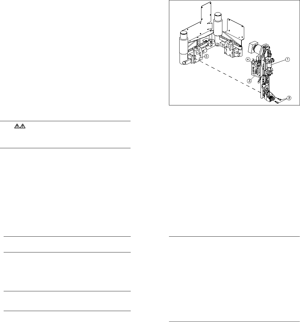
Fig. 10.2.1 Installing / Removing the glue application head
Key to Fig. 10.2.1
1 Glue application head 2
2 Fixing screws for the glue application head (4 x M3 hexagon socket-head screws)
3 Conversion board for gluing head Y0052 (gluing head board)
4 Ribbon cable
5 Angle bracket (supporting plate for dispensing unit) (on glue application heads 1 and 2 only)
10.2.3.1 Removal
● Remove the protective side covers. Manually move the gantry until the glue application head to be
removed is easily accessible. Note the warning given above.
● Detach the ribbon cable from the gluing head board on the glue application head concerned. To do this,
press down on the plug retainers.
● Loosen the four hexagon socket-head screws used to screw the glue application head to the angle bracket
(supporting plate for the dispensing unit) (see Fig. 10.2.1). Carefully remove the glue application head.
● Remove the black air line that leads from the gantry to the dispensing valve of the glue application head.
Do not remove the air line that leads from the dispensing pressure unit to the glue cartridge.
10 Siplace G automatic glue applicator SIPLACE 80S/80F/G Service Manual
Edition 06/98
10 - 10
PLEASE NOTE
The glue application head is pinned to the angle bracket (dispensing unit supporting plate). If the glue
application head cannot be removed immediately, loosen it carefully without using tools.
10.2.3.2 Installation
● Reconnect the black air line to the dispensing valve.
● Place the new glue application head on the angle bracket on the supporting plate.
● Tighten the four hexagon socket-head screws on the glue application head. Secure the hexagon socket-
head screws first with Loctite adhesive. Follow the instructions given below.
PLEASE NOTE
The glue application head 2 differs from glue application heads 1 and 3 (1 and 3 are identical). The glue
application heads have an identification label. When installing, make sure that the glue application heads
are assigned correctly.
● Introduce the black air line through the fixing lugs on the glue application head.
● Connect the ribbon cable to the gluing head board of the glue application head concerned. The plug retain-
ers must fold up fully. Make sure that the cable is inserted correctly.
● Replace the protective side covers in the machine.
● Correct the position as necessary (see instructions below). All other settings associated with the glue
application heads are described in detail in Section 10.3.
● Check the settings of the pressure sensor and temperature sensor on the new glue application head(s).
Readjust the pressure sensor and temperature sensor if necessary (see Section 10.3).
● Check the dynamic behavior of the z axis of the new glue application head(s). Readjust the dynamic
behavior, if necessary (see Section 10.3).
● Once all the settings are complete, carry out a short functional test on the new glue application head(s).
SIPLACE 80S/80F/G Service Manual 10 Siplace G automatic glue applicator
Edition 06/98
10 - 11
PLEASE NOTE
You will then have to carry out various position corrections, in the specified order, regardless of which glue
application head was replaced:
Situation 1: Only glue application head 3 was replaced, glue application heads 1 and 2 were not
changed.
- Record the zero point correction for axis Z3.
- Record the offset between the PCB camera and glue application head 3.
- Record the offset between glue application heads 1 and 2 and glue application head 3.
- Record the machine zero point.
- The following position corrections must be carried out in relation to the new machine zero point:
The automatic width adjustment must be calibrated.
Max/min positions of the X1 and Y1 axes
Situation 2: Only glue application head 1 and/or glue application head 2 was replaced, glue applica-
tion head 3 was not changed.
- Record the zero point correction for axis Z1 and/or Z2.
- Record the offset between glue application head 1 and 2 and glue application head 3.
- The Y2 and/or X2 axis must be mapped.
Situation 3: Glue application head 3, glue application head 1 and/or glue application head 2 was
replaced.
- All the position corrections described for situations 1 and 2 must be carried out.