80S-15贴片机.pdf - 第454页
10 Si plac e G au tom atic g lue ap plic ator SIPLA CE 80 S/80 F/G Servi ce Ma nua l Ed itio n 06 /98 10 - 12 10.2.4 Replacing the Z axi s motor PLEASE NOTE: Do not re move the proximi ty swit ch (BERO) at the top of the…
10 Siplace G automatic glue applicator SIPLACE 80S/80F/G Service Manual
Edition 06/98
10 - 8
10.2.2.1 Tools required
You will need the equipment listed in this section in order to carry out servicing work on the glue applicator
heads.
- 1 set of screwdrivers
- 1 set of hexagon socket screw keys
- 1 x diagonal cutter, small
- 1 x flat-nose pliers
- 1 x caliper
- Screw locking glue (Loctite 462)
- 1 set of drift punches
- 1 x 250 g hammer
- Spare parts catalog
10.2.2.2 Preparatory tasks
Carry out the following preparatory tasks before any maintenance work on the glue application heads. This
will make the work easier and prevent subsequent errors.
● Before starting maintenance, switch off at the main switch and remove the mains plug. Secure the system
to prevent it being switched on again. See also the DANGER instructions at the start of this chapter.
● Remove the glue cartridges together with the spacers from the glue application heads.
10.2.3 Replacing the glue application head
WARNING
Whenever the gantry is moved manually, the Z axes of the glue applications heads have to be in their top
starting position (Z-Null = min. position). In the bottom position (max. Z position) the Z axis can collide with the
comb of the center conveyor causing irreparable damage to the glue application head. Also follow the safety
instructions in Section 10.2.1
SIPLACE 80S/80F/G Service Manual 10 Siplace G automatic glue applicator
Edition 06/98
10 - 9
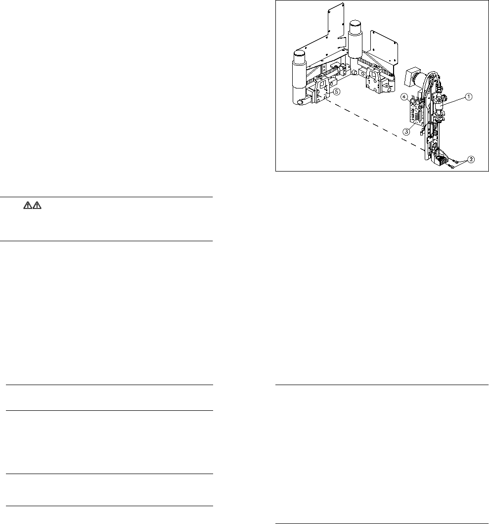
Fig. 10.2.1 Installing / Removing the glue application head
Key to Fig. 10.2.1
1 Glue application head 2
2 Fixing screws for the glue application head (4 x M3 hexagon socket-head screws)
3 Conversion board for gluing head Y0052 (gluing head board)
4 Ribbon cable
5 Angle bracket (supporting plate for dispensing unit) (on glue application heads 1 and 2 only)
10.2.3.1 Removal
● Remove the protective side covers. Manually move the gantry until the glue application head to be
removed is easily accessible. Note the warning given above.
● Detach the ribbon cable from the gluing head board on the glue application head concerned. To do this,
press down on the plug retainers.
● Loosen the four hexagon socket-head screws used to screw the glue application head to the angle bracket
(supporting plate for the dispensing unit) (see Fig. 10.2.1). Carefully remove the glue application head.
● Remove the black air line that leads from the gantry to the dispensing valve of the glue application head.
Do not remove the air line that leads from the dispensing pressure unit to the glue cartridge.
10 Siplace G automatic glue applicator SIPLACE 80S/80F/G Service Manual
Edition 06/98
10 - 10
PLEASE NOTE
The glue application head is pinned to the angle bracket (dispensing unit supporting plate). If the glue
application head cannot be removed immediately, loosen it carefully without using tools.
10.2.3.2 Installation
● Reconnect the black air line to the dispensing valve.
● Place the new glue application head on the angle bracket on the supporting plate.
● Tighten the four hexagon socket-head screws on the glue application head. Secure the hexagon socket-
head screws first with Loctite adhesive. Follow the instructions given below.
PLEASE NOTE
The glue application head 2 differs from glue application heads 1 and 3 (1 and 3 are identical). The glue
application heads have an identification label. When installing, make sure that the glue application heads
are assigned correctly.
● Introduce the black air line through the fixing lugs on the glue application head.
● Connect the ribbon cable to the gluing head board of the glue application head concerned. The plug retain-
ers must fold up fully. Make sure that the cable is inserted correctly.
● Replace the protective side covers in the machine.
● Correct the position as necessary (see instructions below). All other settings associated with the glue
application heads are described in detail in Section 10.3.
● Check the settings of the pressure sensor and temperature sensor on the new glue application head(s).
Readjust the pressure sensor and temperature sensor if necessary (see Section 10.3).
● Check the dynamic behavior of the z axis of the new glue application head(s). Readjust the dynamic
behavior, if necessary (see Section 10.3).
● Once all the settings are complete, carry out a short functional test on the new glue application head(s).
SIPLACE 80S/80F/G Service Manual 10 Siplace G automatic glue applicator
Edition 06/98
10 - 11
PLEASE NOTE
You will then have to carry out various position corrections, in the specified order, regardless of which glue
application head was replaced:
Situation 1: Only glue application head 3 was replaced, glue application heads 1 and 2 were not
changed.
- Record the zero point correction for axis Z3.
- Record the offset between the PCB camera and glue application head 3.
- Record the offset between glue application heads 1 and 2 and glue application head 3.
- Record the machine zero point.
- The following position corrections must be carried out in relation to the new machine zero point:
The automatic width adjustment must be calibrated.
Max/min positions of the X1 and Y1 axes
Situation 2: Only glue application head 1 and/or glue application head 2 was replaced, glue applica-
tion head 3 was not changed.
- Record the zero point correction for axis Z1 and/or Z2.
- Record the offset between glue application head 1 and 2 and glue application head 3.
- The Y2 and/or X2 axis must be mapped.
Situation 3: Glue application head 3, glue application head 1 and/or glue application head 2 was
replaced.
- All the position corrections described for situations 1 and 2 must be carried out.
10 Siplace G automatic glue applicator SIPLACE 80S/80F/G Service Manual
Edition 06/98
10 - 12
10.2.4 Replacing the Z axis motor
PLEASE NOTE:
Do not remove the proximity switch (BERO) at the top of the motor flange when you replace the Z axis motor.
Do NOT change the initial tension of the cam disc bearing when replacing the Z axis motor.
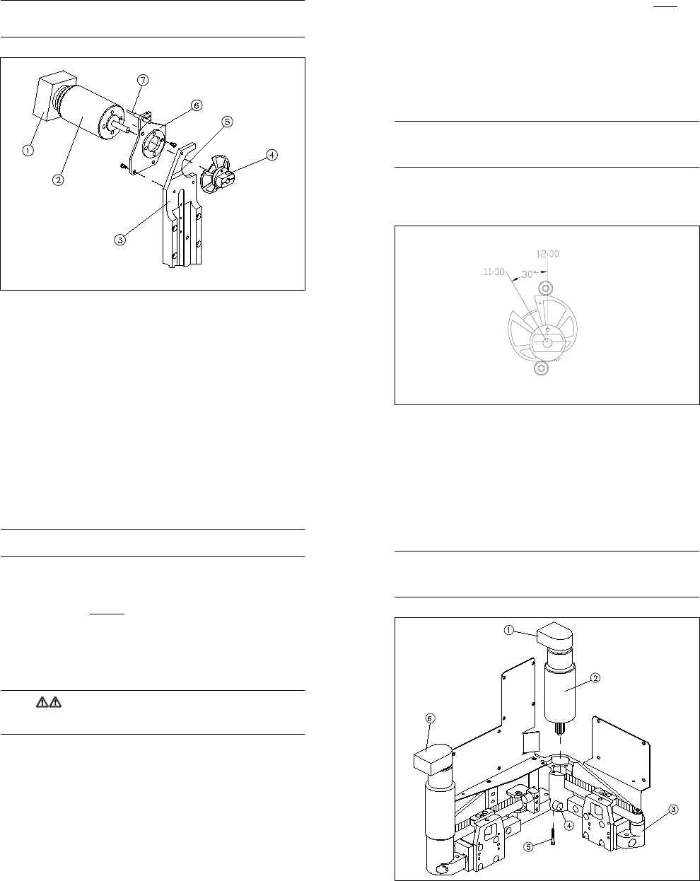
Fig. 10.2.2 Overview: Replacing the Z axis motor for the glue application head
Key to Fig. 10.2.2
1 Incremental encoder
2 Z axis motor
3 Motor support
4 Clamping screw for the hub of the cam disc
5 Round countersunk holes in the motor supports
6 Motor flange
7 Proximity switch (do not remove)
SIPLACE 80S/80F/G Service Manual 10 Siplace G automatic glue applicator
Edition 06/98
10 - 13
10.2.4.1 Removal
● To replace the z axis motor, remove the glue application head as described in Section 10.2.3.
● Loosen the clamping screw for the hub of the cam disc (M3 hexagon socket-head screw). DO NOT loosen
the screw for setting the initial tension of the cam disc bearing.
● Dismantle the motor flange from the motor support by loosening the three fixing screws
(M3 hexagon socket-head screws). These screws are accessible from the motor side.
● Pull the motor and the motor flange out from the back of the glue application head. At the same time, care-
fully remove the cam disc from the motor shaft. It is not necessary to change the initial tension of the cam
disc bearing to do this.
● Loosen the four fixing screws to dismantle the motor flange from the motor.
10.2.4.2 Installation
PLEASE NOTE:
Before assembling the motor flange, turn the motor so that the incremental encoder points downwards (plug
connection pointing to "6 o‘clock"). If the incremental encoder is pointing in another direction, there is a risk of
collision.
● Fit the motor flange to the motor by tightening the four fixing screws (M3 hexagon socket-head screws).
Please note that the incremental encoder must point downwards when the motor is installed.
● Insert the motor from the back into the motor support. At the same time, push the cam disc onto the motor
shaft. The recess in the cam disc should point to "11 o’clock" (see Fig. 10.2.3).
Fig. 10.2.3 Installation position for the cam disc of the z axis
10 Siplace G automatic glue applicator SIPLACE 80S/80F/G Service Manual
Edition 06/98
10 - 14
PLEASE NOTE:
During assembly, push the sides of the motor flange into the round countersunk hole in the motor support.
● Screw the motor flange to the motor support by tightening the three fixing screws. Please note the instruc-
tions above.
● Push the cam disc to the middle of the two cam disc bearings. The recess in the cam disc must be to the
left of the cam disc bearings, at the "11o‘clock" position (see Fig. 10.2.3). Lightly clamp the cam disc.
● Check that the cam disc lies against both cam disc bearings over the entire travel distance and that the
mechanism is running smoothly (you must always be able to turn the cam disc bearings). If this is not the
case, correct the installation position of the motor flange in the motor support.
● Leave the cam disc clamped lightly. Do not tighten it until you have set the zero point correction for the z
axis.
● Reconnect the three plugs (power supply, incremental encoder and inductive switch) to the gluing head
board. Fix the cable around the motor with a cable tie.
● Carry out a zero point correction for the z axis (see Section 10.3).
WARNING
The machine must not be started normally until the zero point correction has been carried out. You may only
load the SIKLEBER test program in order to determine the zero point correction for the z axis.
● Check the dynamic behavior settings for the z axis. If necessary, adjust the dynamic behavior as described
in Section 10.3.
● Calibrate the machine as described for situations 1 - 3 in Section 10.2.3.
SIPLACE 80S/80F/G Service Manual 10 Siplace G automatic glue applicator
Edition 06/98
10 - 15
10.2.5 Replacing the X2/Y2 axis direct-drive motor
PLEASE NOTE
The procedures for replacing the X2 and Y2-axis motors are almost identical. Conesequently, only replace-
ment of the Y2-axis motor will be described here. The wiring of the X2 and Y2-axis motors differs (reversed
direction of rotation at positive travel), so please note this when ordering spare parts.
Fig. 10.2.4 Overview: Replacing the Y2 axis direct-drive motor
Key to Fig. 10.2.4
1 / 6 Incremental encoder for the Y2/X2 axis motor (1 must be aligned at the back and 6 on the left)
2 Y2 axis direct-drive motor
3 Mini-gantry
4 Elastomeric spring (only has to be removed from the Y2 axis motor of the glue application head)
5 Fixing screws for the direct-drive motor (3 x, loosen fully)
10 Siplace G automatic glue applicator SIPLACE 80S/80F/G Service Manual
Edition 06/98
10 - 16
10.2.5.1 Removal
PLEASE NOTE
It is not necessary to dismantle the glue application head in order to remove the direct-drive motor. It is also
unnecessary to slacken the toothed belt.
● Detach the electrical connections on the direct-drive motor to be replaced. To do this, disconnect the two
plugs from the small axis conversion board at the top of the gantry. Remove the cable ties from the small
axis conversion board.
● Loosen the fixing screws on the direct-drive motor (3 x M3 hexagon socket-head screws). The fixing
screws can be accessed from the bottom of the mini-gantry.
For the Y2 axis direct-drive motor only: Remove the elastomeric spring before loosening the third fixing
screw. Hold a hammer at the top of the mini-gantry and tap the clamping collar holding the elastomeric
spring out from below. Use a 3.9 mm diameter drift punch. Then remove the elastomeric spring from the
mini-gantry.
● Lift the direct-drive motor out from the top of the mini-gantry.
10.2.5.2 Installation
● Place the new direct-drive motor in the mini-gantry, making sure that the toothed belt runs around the
toothed belt wheel. The incremental encoder on the direct-drive motor must be aligned at the back (away
from the glue application head).
● Screw in the three fixing screws of the direct-drive motor and secure with Loctite adhesive.
● Only for the Y2 axis direct-drive motor: Refit the elastomeric spring once you have tightened all three fixing
screws. Insert the elastomeric spring in the mini-gantry. Hold a hammer at the top of the mini-gantry and
then tap the clamping collar in from below.
● Connect the two plugs for the direct-drive motor to the small axis conversion board at the top of the gantry.
Fix the cable to the small axis conversion board once more using cable ties.
● Check the tension of the toothed belt and tighten, if necessary. A description of the tensioning process is
given in Section 10.3.
● Run the "Calibrate mini-gantry" function in order to determine the zero point correction and the minimum
and maximum travel distances.
● Check the dynamic behavior of the X2/Y2 axis. If necessary, set the dynamic behavior as described in
Section 10.3.
● Determine the offset between heads 1 and 2 and head 3 (see Section 10.3).
● Map the X2 and Y2 axis (see Section 10.3.3.6, page 10 - 30 -”Mapping the X2/Y2 axes (mini-gantry map-
ping)”).
SIPLACE 80S/80F/G Service Manual 10 Siplace G automatic glue applicator
Edition 06/98
10 - 17
10.2.6 Replacing the toothed belt (X2/Y2 axis drive)
PLEASE NOTE
The procedures for replacing the toothed belts for the X2 and Y2 axes are almost identical. Consequently,
only replacement of the X2 toothed belt will be described here.
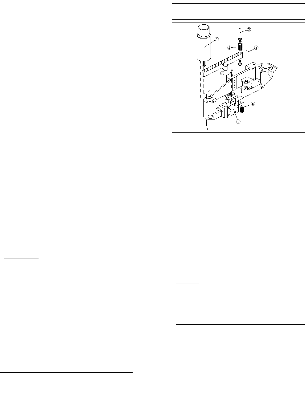
Fig. 10.2.5 Overview: Replacing the toothed belt (X2 axis)
Key to Fig. 10.2.5
1 X axis direct-drive motor
2 Synchronizing disc (deflection pulley)
3 Axle of the deflection pulley
4 Stud bolt for clamping the deflection pulley
5 Fixing screw of the idler pulley
6 Idler pulley
7 Angle bracket
10 Siplace G automatic glue applicator SIPLACE 80S/80F/G Service Manual
Edition 06/98
10 - 18
10.2.6.1 Removal
● Dismantle the direct-drive motor of the mini-gantry axis concerned (see previous section). Do not detach
the electrical connections from the direct-drive motor.
● Open the angle bracket by removing the fixing screw from the idler pulley (1 x M4 hexagon socket-head
screw). Then remove the idler pulley from the toothed belt fastener.
● For the X2 toothed belt only:
● Release the clamping on the deflection pulley. To do this, remove the small stud bolt in the teeth of the
deflection pulley (see Fig. 10.2.5).
● Using a drift punch (diameter 3.9 mm), tap the shaft of the deflection pulley out through the bottom.
● Remove the toothed belt from the machine.
10.2.6.2 Installation
● Thread the new toothed belt into the angle bracket.
● Insert the idler pulley in the angle bracket once more. The toothed belt must wrap around the idler pulley.
Do not fully tighten the fixing screw of the idler pulley.
● For the X2 toothed belt only:
● First place the toothed belt around the deflection pulley and then refit the deflection pulley.
● Clamp the deflection pulley by screwing the small grub screw back into the deflection pulley.
● Insert and tighten the screws of the direct-drive motor (see Section 10.2.5).
● Tension the toothed belt (see Section 10.3).
● Run the "Calibrate mini-gantry" function in order to determine the zero point correction and the minimum
and maximum travel distances.
● Check the dynamic behavior of the X2/Y2 axis. If necessary, set the dynamic behavior as described in
Section 10.3.
● Determine the offset between head 1 and 2 and head 3 (see Section 10.3).
● Map the X2 and Y2 axes (see Section 10.3).
10.2.7 Replacing the dispensing valve
PLEASE NOTE
The dispensing pressure unit has two valves: a dispensing valve and an air relief valve. Before replacing,
check which of the two valves is defective. Then order the correct replacement valve. Replacement of both
the dispensing valve and the air relief valve is described below.
SIPLACE 80S/80F/G Service Manual 10 Siplace G automatic glue applicator
Edition 06/98
10 - 19
10.2.7.1 Removal
● Detach the ribbon cable from the gluing head board of the glue application head. To do this, push down on
the plug retainers.
● Remove the entire dispensing pressure unit from the glue application head. To do this, loosen the fixing
screws on the mount or the separator (2 x M4 hexagon socket-head screws, see Fig. 10.2.6).
● Remove the three plugs from the controller of the dispensing valve/air relief valve (at the bottom of the glu-
ing head board).
● Loosen the four cap nuts and remove the gluing head board from the dispensing pressure unit. When you
do this, pull the pressure sensor connecting tube carefully from the dispensing pressure unit.
● Disconnect the dispensing pressure line from the quick-release coupling of the dispensing pressure unit.
● Disconnect the black air line from the gantry to the dispensing valve.
● Gluing head 2 only: Remove the separator from the dispensing pressure unit. To do this, loosen the fixing
screws on the separator (2 x M3 hexagon socket-head screws).
● First mark the position of the covers on the dispensing pressure unit. Then loosen the fixing screws on the
covers (4 x M3 spacer bolts plus 2 x M3 hexagon socket-head screws). Then carefully lift the cover.
● Remove the cover gasket.
PLEASE NOTE
Mark the position of the dispensing valve on the dispensing pressure unit before removing the valve. You
will also note that there is a hole drilled through one of the two fixing screws of the dispensing valve. Mark
the position of this fixing screw as well.
● Dismantle the dispensing valve by loosening the fixing screws (2 x M3 hexagon socket-head screws) on
the inside of the dispensing pressure unit.
● Loosen the fixing screw of the air relief valve (1 x M10 hex screw) on the inside of the dispensing pressure
unit using a special thin socket spanner.
● Remove the entire dispensing valve and air relief valve from the dispensing pressure unit.