80S-15贴片机.pdf - 第460页
10 Si plac e G au tom atic g lue ap plic ator SIPLA CE 80 S/80 F/G Servi ce Ma nua l Ed itio n 06 /98 10 - 36 10.3.4.3 Adjusting the dispensing pressur e sensor Fig. 10 .3.4 Tes t set -up: Ad justi ng the disp ensin g pr…
10 Siplace G automatic glue applicator SIPLACE 80S/80F/G Service Manual
Edition 06/98
10 - 32
10.3.4 Electrical adjustments
PLEASE NOTE
Always check the set values before you carry out any electrical adjustments. The potentiometers are preset
and only have to be adjusted if the set values are outside the tolerances.
Switch the machine off for at least 30 minutes before making any adjustments (particularly when changing the
temperature).
10.3.4.1 Adjusting the room temperature sensor
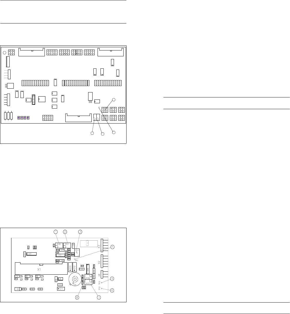
Fig. 10.3.2 Overview: Y0055 conversion board
Key to Fig. 10.3.2
1 Test point TP1 for temperature sensor PT 500
2 Potentiometer R74 for 0V adjustment ( 15
o
C)
3 Potentiometer R73 for 5V adjustment ( 40
o
C)
4 Jumper block X27
X9 X1 3
X1 1
X2 8
X2 9
1
IC1
IC19
X15
X16
X17
R71
R69
R72
R70
R1
R2
R3
IC20
R73
R74
X8 X1 0 X12
X27 X14 X2 3
X24 X25 X2 6
X22 X21 X20 X19 X18
TP1
1
Amplitude
Offset
Amplitude
Offset
Spur A
Spur B
1
3
2
1
4
Amplitude
Offset
Amplitude
Offset
Track A
Track B
^
=
^
=
SIPLACE 80S/80F/G Service Manual 10 Siplace G automatic glue applicator
Edition 06/98
10 - 33
Preparation:
● Load the SIKLEBER test program. Please read the warnings at the start of this chapter.
● A digital voltmeter is used to adjust the room temperature sensor. Set the voltmeter to a measuring range
of 20 V DC.
● Connect the test cable of the voltmeter as follows:
Connect the positive cable to TP1 on the small axis conversion board Y0055 (= board at the top of the gan-
try, see Fig. 10.3.2). Test point 1 is used for temperature sensor PT 500.
Connect the negative cable to TP 3 on board Y0052 (= glue head board, see Fig. 10.3.3). Test point 3 is
the ground terminal.
Adjustment:
● Connect the jumper of jumper block X27 to pin 1/2. Jumper block JP 1 is located on conversion board
Y0055 (see Fig. 10.3.2).
● Select the "Dispens. control" menu, followed by "Peltier functions" and then "Environm. temperature (ambi-
ent temperature)" to display the ambient temperature. Press Return to read the ambient temperature on
the right of the monitor.
● If the jumper setting is correct, the ambient temperature reading will be 15 °C.
● Use potentiometer R 74 to set TP1 to 0V (tolerance ± 20 mV). Potentiometer R 74 is located on conver-
sion board Y0055 (see Fig. 10.3.2).
● The set 0 V voltage corresponds to a temperature of 15 °C (tolerance ± 0.3 °C).
● Then connect the jumper of jumper block X27 to pin 3/4.
● Read the ambient temperature. If the jumper is set correctly the ambient temperature will be 40 °C.
● Use potentiometer R 73 to set TP1 to 5 V (tolerance ± 20 mV). Potentiometer R 73 is located on conver-
sion board Y0055 (see Fig. 10.3.2).
● The adjusted 5 V voltage corresponds to a temperature of 40 °C (tolerance ± 0.3 °C).
PLEASE NOTE
After adjustment, you must replace the jumper on pin 5/6, otherwise the temperature cannot be measured.
● Display the ambient temperature, which should now be approximately the same as the actual room tem-
perature.
10 Siplace G automatic glue applicator SIPLACE 80S/80F/G Service Manual
Edition 06/98
10 - 34
10.3.4.2 Adjusting the temperature sensor
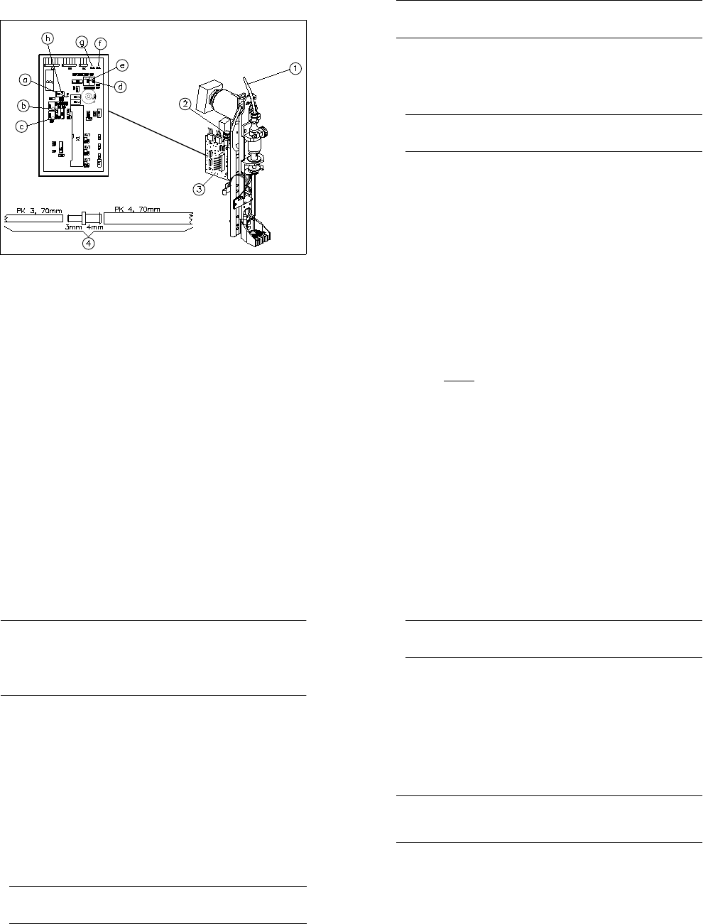
Fig. 10.3.3 Overview: glue head conversion board (glue head board) Y0052
Key to Fig. 10.3.3
1 Potentiometer R26 (-5V temperature sensor setting 40
o
C)
2 Potentiometer R27 (0V temperature sensor setting 15
o
C)
3 Jumper block JP1 (return jumper to pin 5/6 after adjustment)
4 Test point TP1 (heat exchanger signal)
5 Test point TP3 ⊥ (ground)
6 Test point TP2 (dispensing pressure sensor signal)
7 Potentiometer R37 (dispensing pressure sensor setting for Pmax)
8 Potentiometer R38 (0V adjustment ambient pressure)
Preparation:
● Load the SIKLEBER test program. Please read the warnings at the start of this chapter.
● A digital voltmeter is used to adjust the temperature sensor. Set the voltmeter to a measuring range of 20
V DC.
● Connect the test cable of the voltmeter as follows:
Connect the positive cable to TP1 on board Y0052 (= glue head board of the glue application head to be
adjusted, see Fig. 10.3.3). Test point 1 is used for the PT 500 temperature sensor on the heat exchanger.
Connect the negative cable to TP 3 on board Y0052. Test point 3 is the ground terminal.
^
=
^
=
^
=
SIPLACE 80S/80F/G Service Manual 10 Siplace G automatic glue applicator
Edition 06/98
10 - 35
Adjustment:
● Select the "Dispens. control" menu and then "Gluing head 1" (or "2" or "3"), i.e. the glue application head
with the temperature sensor to be adjusted.
● Connect the jumper of jumper block JP 1 to pin 1/2. Jumper block JP 1 is located on glue head board
Y0052 (see Fig. 10.3.3).
● Select the "Dispens. control" menu, followed by "Peltier functions" and then "Actual temperature" to display
the actual temperature on screen. Press the Return key to read the actual temperature on the right of the
monitor.
● If the jumper is set correctly, the actual temperature will read 15 °C.
● Use potentiometer R 27 to set TP1 to 0 V (tolerance ± 20 mV). Potentiometer R 27 is also located on
board Y0052.
● The adjusted 0 V voltage corresponds to a temperature of 15 °C (tolerance ± 0.3 °C).
● Now connect the jumper of jumper block JP 1 to pin 3/4.
● Select the "Dispens. control" menu, followed by "Peltier functions" and then "Actual temperature" to display
the actual temperature on screen. Press the Return key to read the actual temperature on the right of the
monitor.
● If the jumper is set correctly, the actual temperature will read 40 °C.
● Use potentiometer R 26 to set TP1 to 5 V (tolerance ± 20 mV). Potentiometer R 26 is also located on
board Y0052.
● The adjusted 5 V voltage corresponds to a temperature of 40 °C (tolerance ± 0.3 °C).
● Adjust the temperature sensors of the other glue application heads, if necessary.
PLEASE NOTE
After adjustment, you must replace the jumper on pin 5/6, otherwise the temperature cannot be regulated.
10 Siplace G automatic glue applicator SIPLACE 80S/80F/G Service Manual
Edition 06/98
10 - 36
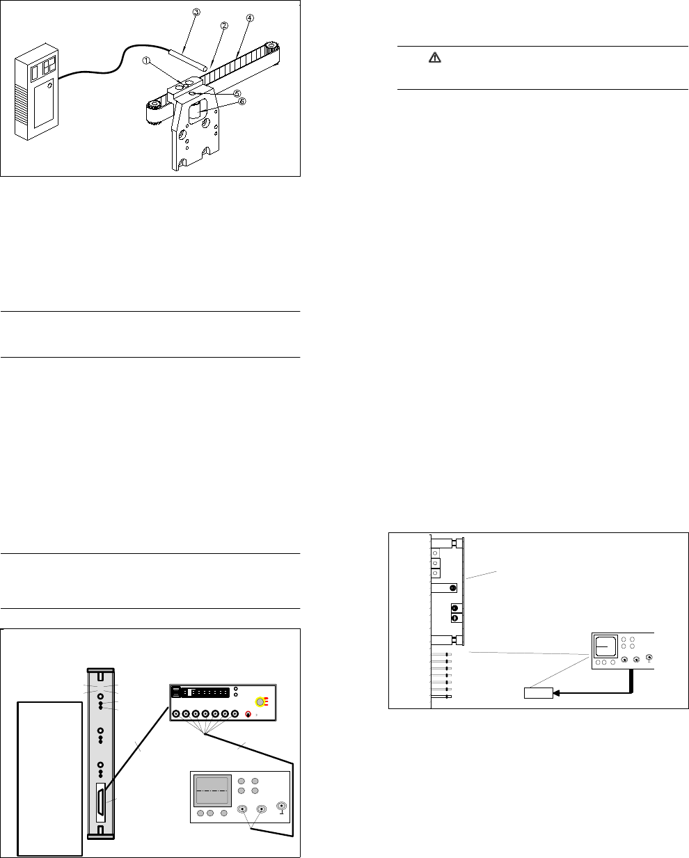
10.3.4.3 Adjusting the dispensing pressure sensor
Fig. 10.3.4 Test set-up: Adjusting the dispensing pressure sensor
Key to Fig. 10.3.4
1 Dispensing pressure line
2 Quick-release coupling for the pressure chamber
3 Glue head conversion board Y0052
4 Adapter hose (prepare as shown in drawing)
a Test point TP1 (heat exchanger signal)
b Potentiometer R27 (0V temperature sensor setting; 15
o
C)
c Potentiometer R26 (5V- temperature sensor setting; 40
o
C)
d Potentiometer R38 (0V setting; ambient pressure)
e Potentiometer R37 (dispensing pressure sensor setting for Pmax)
f Test point TP2 (dispensing pressure sensor signal)
g Test point TP3 ⊥ (ground)
h Jumper block JP1 (replace jumper on pin 5/6 after adjustment)
^
=
^
=
^
=
SIPLACE 80S/80F/G Service Manual 10 Siplace G automatic glue applicator
Edition 06/98
10 - 37
PLEASE NOTE
Prepare an adapter hose made of a ∅ 3 mm PU hose approximately 70 mm long, a ∅ 3 mm to ∅ 4 mm reduc-
ing adapter (metal) and a ∅ 4 mm PU hose approximately 70mm long (see Fig. 10.3.4, item 4).
Preparation:
● Load the SIKLEBER test program. Please read the warnings at the start of this chapter.
● Switch the control on.
● Detach the dispensing pressure line (Fig. 10.3.4, item 1) from the quick-release coupling of the pressure
chamber (Fig. 10.3.4 item 2). Insert the ∅ 3 mm end of the adapter hose into the quick-release coupling of
the pressure chamber.
PLEASE NOTE
When you insert air hoses into quick-release connections, ensure that you push them in as far as the sec-
ond perceptible stop.
● A digital voltmeter is used to adjust the dispensing pressure sensor. Set the voltmeter to a measuring
range of 20 V DC.
● Connect the test cable of the voltmeter as follows:
Connect the positive cable to TP2 on board Y0052 (= gluing head board of the glue application head to be
adjusted, see Fig. 10.3.4). Test point 2 is used for the dispensing pressure sensor IC 5.
Connect the negative cable to TP 3 on the same board (Y0052). (Test point 3 is the ground terminal).
● Select the "Dispens. control" menu, followed by "Gluing dots" and then "Adjust pressure" to set the dis-
pensing pressure. Use the arrow keys ↑ and ↓ to change the pressure. Set the pressure to 5.115 bar and
then press the ESC key to accept the setting.
● Select the "Dispens. control" followed by "Gluing head 1" or 2/3 to select the glue application head with the
dispensing pressure sensor to be adjusted.
Adjustment:
● Do not close the open end of the adapter hose (= ambient pressure of 0 bar).
● Use potentiometer R38 (left potentiometer) on board Y0052 to set the signal at TP2 to 0 V (tolerance ± 20
mV). The adjusted 0 V voltage corresponds to a pressure of 0 bar.
● Connect the ∅ 4 mm side of the adapter hose to connector B (overpressure) of the compressed air testing
device.
● Select the "Dispens. indefinitely (apply as required)" menu to switch on the pressure in the dispensing
chamber (5.115 bar). Press the spacebar once to pressurize the pressure chamber. Press the spacebar
again to depressurize.
● Calculate the voltage using the following formula:
5.0 V
x measured pressure in bar = voltage to be set
5.115 bar
● Use potentiometer R37 (right potentiometer) on board Y0052 to set the signal at TP2 to the calculated volt-
age. Press the spacebar to depressurize the valve chamber.
10 Siplace G automatic glue applicator SIPLACE 80S/80F/G Service Manual
Edition 06/98
10 - 38
● Remove the adapter hose from the quick-release coupling in the pressure chamber (Fig. 10.3.4 item 2)
and reconnect the original hose (Fig. 10.3.4 item 1).
● Adjust the dispensing pressure sensors on the other glue application heads if necessary.
10.3.4.4 Checking the seals of the dispensing pressure unit
PLEASE NOTE
It is only necessary to check the seals if the dispensing pressure unit has been dismantled (e.g. after replac-
ing the dispensing valve or air relief valve). During the seal test, a constant pressure must be measured in the
pressure chamber over a period of five minutes. After five minutes, the maximum pressure loss must not
exceed 10 % of the initial value.
The constant pressure may be measured using either a voltmeter or a manometer. Both methods are
described below.
● Initial situation: The dispensing pressure unit is connected to the air and power supplies, but is not yet
screwed to the glue application head.
● Load the SIKLEBER test program. Please read the warnings at the start of this chapter.
● Switch the control on.
● For the pressure measurement with a manometer only: Connect the manometer to the dispensing pres-
sure line of the dispensing pressure unit. The connection must be absolutely airtight.
The next two steps relate to pressure measurement with a voltmeter and may be skipped.
● Seal the dispensing pressure line on the dispensing pressure unit (the dispensing pressure line is the air
line leading to the cartridge). To do this, insert a dummy hose or similar into the quick-release coupling of
the pressure chamber. The connection must be absolutely airtight.
● Set a voltmeter to a measuring range of 20 V DC. Connect the test cable of the voltmeter as follows:
Connect the positive cable to TP2 on board Y0052 (= gluing head board of the dispensing pressure unit to
be tested, see Fig. 10.3.3). Connect the negative cable to TP 3 on the same board (Y0052).
● Select the "Dispens. control" menu and then "Gluing head 1" or 2/3 to select the glue application head of
the dispensing pressure unit to be tested.
● Select the "Valve functions" menu and then the "Release pressure" option to vent the dispensing pressure
unit. Press Return to vent the unit. The voltmeter or manometer must display the following value: 0 V (tol-
erance + 20 mV) or 0 bar (tolerance + 0.02 bar).
PLEASE NOTE
If the voltage is outside the tolerance specified above after venting the dispensing pressure unit, the dis-
pensing pressure sensor must be adjusted as described in the previous section.
● Select the "Dispens. control" menu, followed by "Gluing dots" and then "Adjust pressure" to set the dis-
pensing pressure to 5.115 bar (maximum dispensing pressure). Use the arrow keys ↑ and ↓ to change the
pressure. Then press the ESC key.
SIPLACE 80S/80F/G Service Manual 10 Siplace G automatic glue applicator
Edition 06/98
10 - 39
● Switch on the dispensing valve of the dispensing pressure unit by activating the top manual control of the
dispensing valve. The pressure chamber will then be pressurized.
● Switch the dispensing valve over by activating the right manual control of the dispensing valve with a thin
steel plate. This will “enclose“ the pressure in the pressure chamber. Once you have done this, do NOT
aerate or vent the pressure chamber.
● The voltmeter or manometer must display the following value: 5 V (tolerance ± 20 mV) or 5.115 bar (toler-
ance ± 0.02 bar).
PLEASE NOTE
If the voltage is outside the tolerance specified above after venting the dispensing pressure unit, the dis-
pensing pressure sensor must be adjusted as described in the previous section.
● Wait five minutes. Then read the value from the voltmeter or manometer again. The pressure loss must not
exceed 10 % of the initial pressure.
Minimum value on the voltmeter: 4.50 Volt; minimum value on the manometer: 4.60 bar.
● If the values fall below the values specified above, the dispensing pressure unit must be sealed or
replaced. Then check the seals again.
● If the dispensing pressure unit is airtight, remove the dummy hose or manometer. You will hear any resid-
ual pressure dissipating from the pressure chamber.
● Check the seals of the other dispensing pressure units, if necessary.
10.3.5 Tensioning the toothed belt of the X2/Y2 axis
PLEASE NOTE
The correct belt tension of the toothed belt on the X2/Y2 axis is extremely important for precise positioning. It
is only necessary to set the belt tension if the angle bracket has been released. It is absolutely essential to set
the belt tension after replacing the X2/Y2 axis direct-drive motor.
● Open the protective cover and push the gantry into an easily accessible position. Press an emergency
stop button as well.
● You must dismantle the glue application head in order to tension the toothed belt. Read the instructions on
removing the gluing heads in Section 10.2.3.
10 Siplace G automatic glue applicator SIPLACE 80S/80F/G Service Manual
Edition 06/98
10 - 40
● Move the gluing head holder to the minimum position.
Fig. 10.3.5 Overview: Tensioning the toothed belt on the X2 axis (illustrated without glue application head)
Key to
1 Free hole for moving the idler pulley
2 Test point (half-way along the free belt length)
3 Measuring head (illustrated without the stand)
4 Free end of the belt
5 Fixing screw for the idler pulley
6 Idler pulley
● Attach the belt tension measuring device. Position the measuring head just beside the free end of the belt
(approximately 5 - 20 mm). The test point is around half-way along the free belt length (see Fig. 10.3.5).
● Switch on the belt tension measuring device. If "LO BAT" appears on the display, the battery will have to be
charged first.
● Strike the belt sharply to start it vibrating.
PLEASE NOTE
The belt must not be twisted when you strike it since this would make it wobble as it vibrates. Consequently,
as far as possible, you should strike the belt over the entire width. Use an appropriate tool to strike the belt,
e.g. an Allen key. Do NOT strike the belt with your finger.
● The measurement is indicated on the belt tension measuring device in the form of an audible signal. The
measured frequency appears on the display.
● Tensioning the toothed belt:
● Loosen the fixing screw on the idler pulley (see Fig. 10.3.5).
SIPLACE 80S/80F/G Service Manual 10 Siplace G automatic glue applicator
Edition 06/98
10 - 41
● Push a suitable pin (e.g. drift punch or screwdriver) into the free hole in the toothed belt fastener.
● Use the pin to press the idler pulley against the toothed belt (see Fig. 10.3.5). You could also use the
fixing screw to push the idler pulley. At the same time, tighten the fixing screw of the idler pulley once
more.
● Change the belt tension until the required frequency is reached:
182 Hz (for both toothed belts).
CAUTION
The toothed belt can become stretched if it is overtightened. Precise positioning is not possible if the
toothed belt is stretched.
● Remove the belt tension measuring device.
● Mount the glue application head.
● Close the protective cover and release the emergency stop button.
10 Siplace G automatic glue applicator SIPLACE 80S/80F/G Service Manual
Edition 06/98
10 - 42
10.3.6 Adjusting the dynamic behavior of the axes
PLEASE NOTE
- It is only necessary to fundamentally change the dynamic behavior of the axes after certain servicing work,
so check the dynamic behavior before you make any changes.
- Switch the machine on for at least half an hour before you make any adjustments.
- Always adjust the axis boards before adjusting the dynamic behavior of the axes (see Section 10.3.6.1).
Fig. 10.3.6 Test set-up for axis boards
o
o
Endemeldung
Aus / Ein
Initialisiert
O - Impuls
Soll - Poti
Kraft - Poti
Schnittstelle für die
Meßbox
o
o
oo
oo
o
o
oo
oo
o
o
oo
oo
1. Achse 1 Analogmasse
2. Achse 1 Geschwindigkeit
4. Ac hse 1 Endemeldung
3. Achse 1 Kraft
5. Achse 1 Spur A
6. Achse 1 Spur B
7. Achse 1 Nullimpuls
8. Achse 2 Anzeigesignal
9. Achse 2 Geschwindigkeit
11. Achse 2 Endemeldung
10. Achse 2 Kraft
12. Achse 2 Spur A
13. Achse 2 Spur B
14. Achse 2 Nullimpuls
15. Achse 3 Anzeigesignal
16. Achse 3 Geschwindigkeit
18. Achse 3 Endemeldung
17. Achse 3 Kraft
19. Achse 3 Spur A
20. Achse 3 Spur B
21. Achse 3 Nullimpuls
22. GND
23. + 5V-
24. +15V-
25. - 15V-
Steckerbelegung
( Meßbox )
Achse 1
Achse 2
Achs e 3
Reset
AUS
EIN
Nullimpuls
Endemeldu ng
Spur A Spu r B Nullimpuls Sollwert Kraft
Ende
Meldung
Positions
Abweich ung
Synchronisierung
0,1 V^
=
1 Digit
SIEMENS AG
AUT51 - QS
CH1 CH2
XY
Verbindungskabel
BNC-Kabel
Zero pulse
End signal
Connection cable
Test box interface
BNC cable
1. Axis 1 Analog ground
2. Axis 1 Speed
3. Axis 1 Power
4. Axis 1 End signal
5. Axis 1 Track A
6. Axis 1 Track B
7. Axis 1 Zero pulse
8. Axis 2 Display signal
9. Axis 2 Speed
10. Axis 2 Force
11. Axis 2 End signal
12. Axis 2 Track A
13. Axis 2 Track B
14.Axis 2 Zero pulse
15. Axis 3 Display signal
16. Axis 3 Speed
17. Axis 3 Force
18. Axis 3 End signal
19. Axis 3 Track A
20. Axis 3 Track B
21.Axis 3 Zero pulse
22.GND
23.+ 5 V-
24.+ 15 V-
25.- 15 V-
Plug assignment
test box
Initialized
Off/On
Vnom potentiom.
Force potentiom.
SIPLACE 80S/80F/G Service Manual 10 Siplace G automatic glue applicator
Edition 06/98
10 - 43
Fig. 10.3.7 Test set-up for servo boards
10.3.6.1 Adjusting the axis boards
Use the SIPLACE axis testing device to set the axis boards.
● Connect the input of the axis testing device to the axis board to be set (see Fig. 10.3.6).
● Connect a digital multimeter to the "v
nominal
" socket on the back of the axis testing device.
● Set the axis selector switch to the axis to be tested.
● Use the "Setpoint" potentiometer on the front of the axis board (see Fig. 10.3.6) to set
0V ±2mV.
● Connect a digital multimeter to the "Force" socket on the back of the axis testing device.
● Use the "Force" potentiometer on the front of the axis board (see Fig. 10.3.6) to set
0V ±2mV.
● Repeat the procedure for all the axes (3 per axis board).
Offset Drehzahlregler
Impulsstrom Isp. über Festwiderstand
Verstärkung P Ant.
Tacho V
Effektivstrom I eff über Festwiderstand
grün = Betriebsbereit
rot = Störung / Tachobruch bei X- und Y - Achse
MP1 Drehzahlsollwert
MP2 Stromsollwert
MP3 Ausgang Stromregler
MP4 Stromgrenzwert extern
MP5 Tachospannung
MP6 Stromistwert
Flügelplatine
gel b
grün
rot
0 V
gelb = I t - Meldung
2
CH1 CH2
X
Y
Oszillograph
green
yellow
red
yellow = I²t message
green = standby
red = fault / tacho break on X and Y axis
Wing-type board
Speed regulator offset
P gain
Tacho gai n
Power pulse current lsp over fixed resistance
I
r.m.s
current over fixed resistance
Oscillograph
0V
MP1 Speed offset
MP2 Current setpoint value
MP3 Current regulator output
MP4 External current threshold
MP5 Tacho voltage
MP6 Actual current value
RC-Filter