80S-15贴片机.pdf - 第468页
SIPLACE 80S/F/G Service Manual 11 Control Unit Edition 04/97 11 - I Contents Page 11 Control Un it 11.1 Repla cing Modules . . . . . . . . . . . . . . . . . . . . . . . . . . . . . . . . . . . . . . . . . . . . . . . . .…
10 Siplace G automatic glue applicator SIPLACE 80S/80F/G Service Manual
Edition 06/98
10 - 64
Fig. 10.4.4 Small axis conversion board Y0055, ES 5
Key to Fig. 10.4.4
Test points X 28:
- X28, 4/6 RSF input, 1.2V
PP
(+ 0.1V)
- X28, 1/2/3 output of 5V gate, square-wave
- X28, 5/7 output of amplifier, 1.8V
PP
- X29: Place jumper for counting direction between PIN 1 and PIN 2
10.4.2 Adjusting the symmetry and amplification on the measuring sys-
tem
● Set the selector switch of the tester measuring system to "Oscilloscope cal".
● Connect channel 1 and 2 of your oscilloscope to the "Track A" and "Track B" BNC socket of the tester
measuring system.
● Set the voltage range of your oscilloscope to 0.2 V/Div. (see Table 10.4 - 1)
● Move the two beams so that they cover the center line of the screen.
X9 X1 3
X1 1
X2 8
X2 9
1
IC1
IC19
X15
X16
X17
R71
R69
R72
R70
R1
R2
R3
IC20
R73
R74
X8 X1 0 X12
X27 X14 X2 3
X24 X25 X2 6
X22 X21 X20 X19 X18
TP1
1
Amplitude
Offset
Amplitude
Offset
Spur A
Spur B
1
Amplitude
Offset
Amplitude
Offset
Track A
Track B
SIPLACE 80S/80F/G Service Manual 10 Siplace G automatic glue applicator
Edition 06/98
10 - 65
● Select X-Y mode on your oscilloscope.
● Move the light beam until it is exactly in the middle of the screen.
● Set the selector switch of the tester measuring system to "Sine-wave amplifier input"
● Manually move the gantry quickly backward and forward. The following image should appear on screen
(see Fig. 10.4.5):
Fig. 10.4.5 Signal at the sine-wave amplifier input, cannot be set electrically
Input Test point Signal Coupling Y deflection Trigger X deflection
CH1 Measuring
system
BNC socket
of tester
Track A DC 0.2 V/Div
X-Y mode
GND
CH2 Measuring
system BNC
socket of
tester
Track B DC 0.2V/Div
GND
Tab. 10.4 - 1 Parameters for setting the oscilloscope: Setting the track signals
Track setting in X / Y mode
Track A
CH2: 200 mV
Track B
10 Siplace G automatic glue applicator SIPLACE 80S/80F/G Service Manual
Edition 06/98
10 - 66
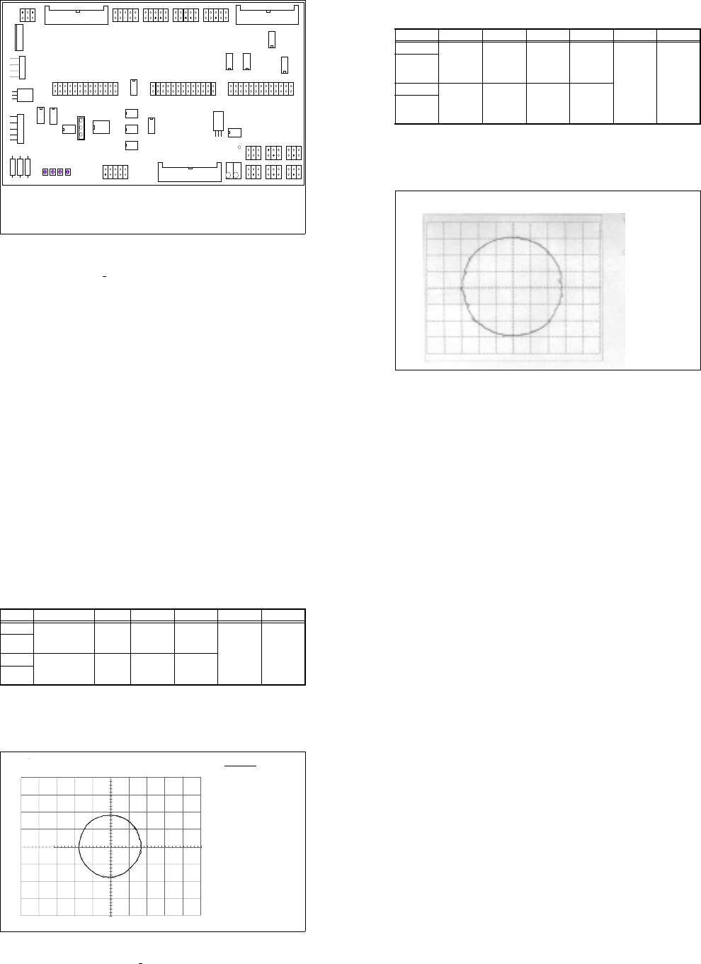
● Set the selector switch of the tester measuring system to "Oscilloscope cal".
● Set the voltage range of your oscilloscope to 0.5 V/Div. (see Table 10.4 - 2)
● Move the two beams so that they cover the center line of the screen.
● Select X-Y mode on your oscilloscope.
● Move the light beam until it is exactly in the middle of the screen.
● Set the selector switch of the tester measuring system to "Sine-wave amplifier output."
● Manually move the gantry quickly backward and forward.
● Use the "Offset" and "Amplification" potentiometers on the board concerned to move the circle on the
screen until the diameter is 1.8 V and its center is in the middle of the screen (see Fig. 10.4.6).
Fig. 10.4.6 Signal at the sine-wave amplifier output, can be set electrically
● If you cannot make the setting as described above, check the mechanical setting of the distance between
the scanning head and the track rule (0.4 mm +
0.05 mm).
❏
Input Test point Signal Coupling Y deflection Trigger X deflection
CH1 Measuring system,
BNC socket of
tester
Track A DC 0.5 V/Div
X-Y mode
GND
CH2 Measuring sys-
tem, BNC socket
of tester
Track B DC 0.5V/Div
GND
Tab. 10.4 - 2 Parameters for setting the oscilloscope
DATE : Mai
23/95
TIME : 13 : 35 : 15
Spur A
CH2: 500mV v.500mV
Spur B
Spureinstellung im X / Y - Betrieb
Track settings in the X / Y operation
Track A
CH2: 200 mV
Track B

SIPLACE 80S/F/G Service Manual 11 Control Unit
Edition 04/97
11 - I
Contents
Page
11 Control Unit
11.1 Replacing Modules. . . . . . . . . . . . . . . . . . . . . . . . . . . . . . . . . . . . . . . . . . . . . . . . . . . . . . .11 - 3
11.1.1 Auxiliary Materials and Equipment Required . . . . . . . . . . . . . . . . . . . . . . . . . . . . . . . . . . . . 11 - 3
11.1.2 Preparatory Work . . . . . . . . . . . . . . . . . . . . . . . . . . . . . . . . . . . . . . . . . . . . . . . . . . . . . . . . .11 - 3
11.1.3 Replacing the Machine Controllers M18. . . . . . . . . . . . . . . . . . . . . . . . . . . . . . . . . . . . . . . . 11 - 4
11.1.4 Replacing Station Computer M34. . . . . . . . . . . . . . . . . . . . . . . . . . . . . . . . . . . . . . . . . . . . . 11 - 5
11.1.5 Replacing the Hard Disk / Floppy Disk Board . . . . . . . . . . . . . . . . . . . . . . . . . . . . . . . . . . .11 - 6
11.2 Set-Up Configuration of the M34 Station Computer . . . . . . . . . . . . . . . . . . . . . . . . . . . . 11 - 7
11.2.1 Configuration Data . . . . . . . . . . . . . . . . . . . . . . . . . . . . . . . . . . . . . . . . . . . . . . . . . . . . . . . .11 - 7
11.2.1.1 Screen 1. . . . . . . . . . . . . . . . . . . . . . . . . . . . . . . . . . . . . . . . . . . . . . . . . . . . . . . . . . . . . . . . 11 - 7
11.2.1.2 Screen 2. . . . . . . . . . . . . . . . . . . . . . . . . . . . . . . . . . . . . . . . . . . . . . . . . . . . . . . . . . . . . . . . 11 - 8
11.2.1.3 Screen 3. . . . . . . . . . . . . . . . . . . . . . . . . . . . . . . . . . . . . . . . . . . . . . . . . . . . . . . . . . . . . . . . 11 - 8
11.3 Wrap Connections of the Station Computer . . . . . . . . . . . . . . . . . . . . . . . . . . . . . . . . . . 11 - 9
11.3.1 KSP-M34-A162 Station Computer . . . . . . . . . . . . . . . . . . . . . . . . . . . . . . . . . . . . . . . . . . . .11 - 9
11.3.2 IEC-Bus Module . . . . . . . . . . . . . . . . . . . . . . . . . . . . . . . . . . . . . . . . . . . . . . . . . . . . . . . . . .11 - 9
11.4 Wrap Connections of Machine Controller MC1 (left-hand side) . . . . . . . . . . . . . . . . . 11 - 10
11.4.1 KSP-M18-A16 C8451-A45-A52-X Machine Controller . . . . . . . . . . . . . . . . . . . . . . . . . . 11 - 10
11.5 Wrap Connections of Machine Controller MC2
(right-hand side, applies to 80S only). . . . . . . . . . . . . . . . . . . . . . . . . . . . . . . . . . . . . . . 11 - 11
11.5.1 KSP-M18-A16 C8451-A45-A51-X Machine Controller . . . . . . . . . . . . . . . . . . . . . . . . . . 11 - 11

11 Control Unit SIPLACE 80S/F/G Service Manual
Edition 04/97
11 - II