80S-15贴片机.pdf - 第477页
11 Control Unit SIPLACE 80 S/F/G Service M anual Edition 04/97 11 - 8 11.2.1. 2 Screen 2 > Bios < En abled D000: Dis abled E000: Disab led > Video < Enabl ed D40 0: Disabl ed E400: Disabled Disabl ed D800: Di…

SIPLACE 80 S/F/G Service Manual 11 Control Unit
Edition 04/97
11 - 7
11.2 Set-Up Configuration of the M34 Station Computer
NOTE
To change the data you will need to use the numerical keypad. This is included in a normal keyboard. The
keys are marked with violet numbers and characters in their top left corner (for example, keys 7-0, U-P, J-ö,
and so on).
Press the Fn key to activate the numerical keypad function of the individual keys.
11.2.1 Configuration Data
11.2.1.1 Screen 1
Date: dd. mmm yyyy
Time: hh:mm:ss
Drive A: 1.44, 3 ½ in.
Drive B: None
Video: EGA / VGA
Post message: Maximize
Quick boot: Disable
Halt on: ALL errors
Security: Disable
Virus Warury: Disable
Booting sequence: A, C
Default speed: High
Disk 0 49 (automatic hard disk detection)
Disk 1 None

11 Control Unit SIPLACE 80 S/F/G Service Manual
Edition 04/97
11 - 8
11.2.1.2 Screen 2
> Bios < Enabled D000: Disabled E000: Disabled
> Video < Enabled D400: Disabled E400: Disabled
Disabled D800: Disabled E800: Disabled
Disabled DC00: Disabled EC00: Disabled
External cache: Enabled Default speed: High
Internal cache: Enabled Slow setting: Fast
COM A: 3F8h
COM B: 2F8h Console rediv: Enable / ANSI
LPT: 378h
Floppy drive: Enabled
IDE: Enabled
11.2.1.3 Screen 3
I/O selection RAM window SMP memory window SMP COM1/2: Disabled
Start address 0000H Start address 0000 00H SMP COM3/4: Disabled
End address 0000H End address 0000 FFH SMP LPT 2: Disabled
SIPLACE 80 S/F/G Service Manual 11 Control Unit
Edition 04/97
11 - 9
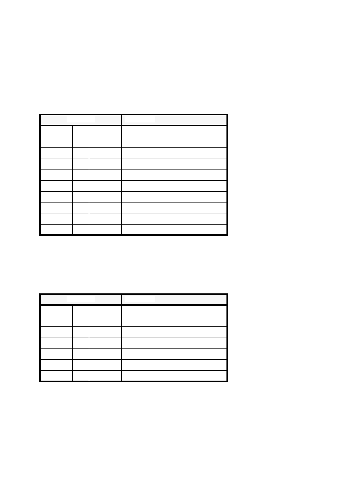
11.3 Wrap Connections of the Station Computer
11.3.1 KSP-M34-A162 Station Computer
The following jumpers must be present:
11.3.2 IEC-Bus Module
The following jumpers must be present:
Connection Significance
WL2/1
→
WL2/2
Primary adapter, color
WM1/1
→
WM1/2 AMS-INIT connected to assembly
WJ1/1
→
WJ1/2 BCLK on AMS-Bus
WL1/10
→
WL1/11 CCLK on AMS-Bus
WM2/1
→
WM2/2 32 KHz cycle connected to RTC
WL1/3
→
WL1/4 XACK on AMS bus
WM1/7
→
WM2/10 AMS-INT4 on IREQ12
WM1/8
→
WM2/11 AMS-INT5 on IREQ15
WJ1/8
→
WM1/10 SW-INT0 on AMS-INT7
WJ1/9
→
WM1/9 SW-INT1 on AMS-INT6
Tab. 11.3 - 1 Wrap connections of station computer KSP-M34-A162
Connection Significance
WJ1/2
→
WJ2/2 TI9914A switched on
WJ1/4
→
WJ2/4 I/O basic address 2B8H
WJ1/6
→
WJ2/6
WM1/3
→
WM2/3 DACK1
WM1/6
→
WM2/6 DRQ1
WM1/10
→
WM2/10 IRQ1
Tab. 11.3 - 2 Wrap connections of the IEC-bus module