00193888-0402_AI_LBO_HFXD3_DE EN - 第37页
Long board 2 Assembly instructions: Long board opt ion - SIPLACE HF-series / X-series / D3 02/2007 Edition 37 2.5.3 Work in processing area 1 : Remove the protective cover over the cable duct. : Remove the cover over the…
2 Assembly instructions: Long board option - SIPLACE HF-series / X-series / D3 Long board
02/2007 Edition
36
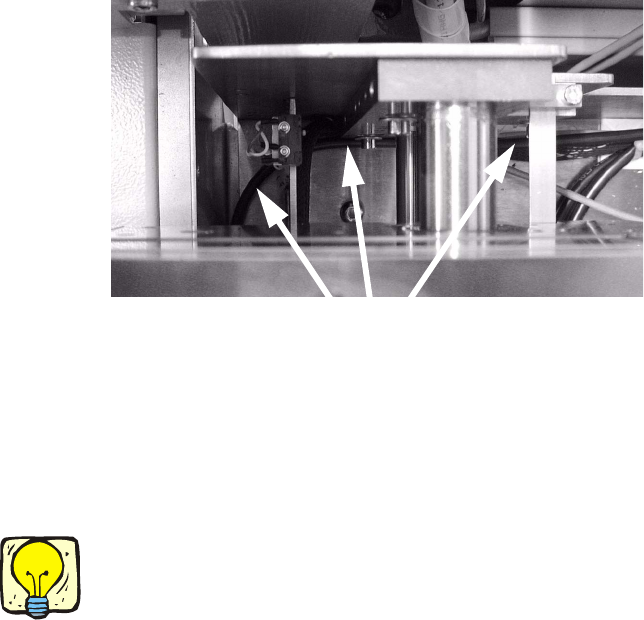
: Run the cables and hose to the cable duct without bending.
: Fix the cables and hoses in the corner of the conveyor side wall using cable ties since the width
adjustment unit moves in this area.
2
2
: Run the connecting cable in the cable duct to the conveyor conversion board, and plug the ca-
ble into the relevant slots on the conversion board (00372253-01):
X34 for processing area 1,
X 35 for processing area 2.
2
The area around the conversion board is quite dark, so you may find it helpful to use a torch. 2
2
: Stow the excess cable in the cable duct.
: Run the compressed air hose through the cable duct into processing area 1.
2
2
2
2
2
2
2
2
Fix cables and hoses in the corner
Long board 2 Assembly instructions: Long board option - SIPLACE HF-series / X-series / D3
02/2007 Edition
37
2.5.3 Work in processing area 1
: Remove the protective cover over the cable duct.
: Remove the cover over the cable duct.
2
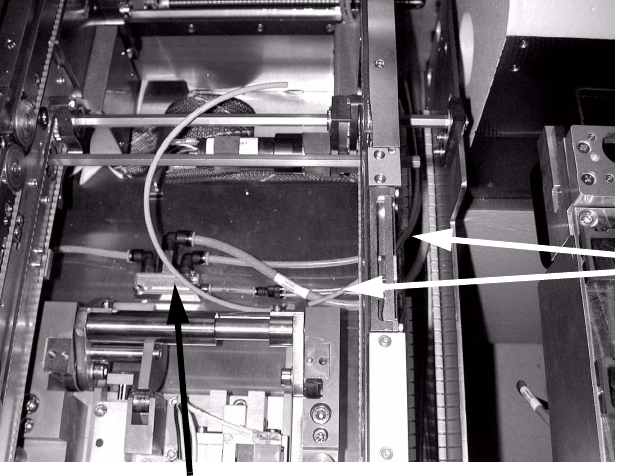
: Pull the compressed air hose that runs through the cable duct from processing area 2 out of
the duct in order to supply air to the conveyor in processing area 1.
2
2
2
2
2
2
2
2
2
2
2
2
Compressed air supply to conveyor
Hose to processing
area 2
2 Assembly instructions: Long board option - SIPLACE HF-series / X-series / D3 Long board
02/2007 Edition
38
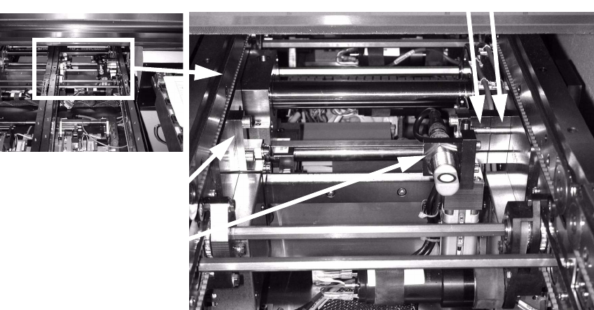
: Attach the unit to the stationary conveyor side wall using two spacer blocks (2 screws).
Before installation, it may be necessary to move a cable tie with base (see photograph below).
: Fit the actuator to the moving conveyor side wall (using 2 screws).
In processing area 1, the actuator is fitted without a spacer block (see photograph below).
: Set the stopper position using the LBO HF assembly gauge.
The adjustments are carried out using the adjusting gauge. See Section 2.5.4 for setting.
2
2
2
2
2
2
2
2
2
2
2
2
2
Unit
Actuator
2 spacer blocks