00193888-0402_AI_LBO_HFXD3_DE EN - 第40页
2 Assembly instructions: Long board option - SIPLACE HF -series / X-series / D3 Long board 02/2007 Edition 40 : Fix the cables and air ho ses so that they do no t rub against any moving p arts, such as wid th adjustment …
Long board 2 Assembly instructions: Long board option - SIPLACE HF-series / X-series / D3
02/2007 Edition
39
: Connect the connecting cable to the unit.
: Connect the hose supplied to the quick-release coupling on the unit.
: Run the connecting cable through the cable duct to the conversion board and plug it in (location
X34).
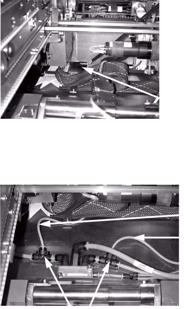
2
: Stow the excess cable in the cable duct on the side.
: Detach the 6 mm hoses on both sides of the air supply, and fit the T-pieces supplied between
the hoses and connection (see photograph below).
Two T-pieces are required on each side for the dual conveyor.
: Attach the supply hoses for the stopper units to the T-pieces.
2
Run the cables through the
opening in the conveyor to
the conversion board.
T-pieces
Hose to unit
PA 1
Hose to unit PA1
Hose to unit
PA 2
2 Assembly instructions: Long board option - SIPLACE HF-series / X-series / D3 Long board
02/2007 Edition
40
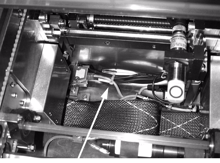
: Fix the cables and air hoses so that they do not rub against any moving parts, such as width
adjustment unit, lifting table, etc.
2
: Close all open cable ducts in both processing areas.
: Attach the protective covers over the cable ducts in both processing areas.
: Attach the lifting table beds in both processing areas.
2
: Close all the safety devices.
: Switch the placement machine on at the main switch.
2
2
2.5.4 Adjusting the stopper units
: Set the conveyor width to 200 mm.
: Switch on the laser light barrier via the I/O functions in SITEST (see Section 2.7).
: Use the I/O functions to extend the stopper.
: Use the adjusting gauge to check the dimension 160 mm.
Fix cables and hoses
Long board 2 Assembly instructions: Long board option - SIPLACE HF-series / X-series / D3
02/2007 Edition
41
: Place the adjusting gauge in the conveyor and push it against the stopper.
The gauge must lie against the stopper and the stationary conveyor side wall.
2
2
: Check whether the laser beam can be seen on the entire front edge of the adjusting gauge. If
this is not the case, adjust the stopper so that the laser beam is visible.
To do this, loosen the fixing screws on the stopper, align the stopper and then tighten the
screws once more.
2
2
Adjusting
gauge
Stopper
Laser light barriers
Laser dots must be visible.