00198171-02_Technical_Training_FSE_TX-Series_EN.pdf - 第106页
7 Power Supply 7.9 Cable harness interface 106 Technical Training FSE SIPLACE TX-Series 01/2018 1. -X23 Mini-Mate.-N-Look 15pol Control elements 1 2. -X24 Mini-Mate.-N-Look 15pol Control elements 2 3. -X26 Mini-Mate.-N-L…
7 Power Supply
7.9 Cable harness interface
Technical Training FSE SIPLACE TX-Series 01/2018 105
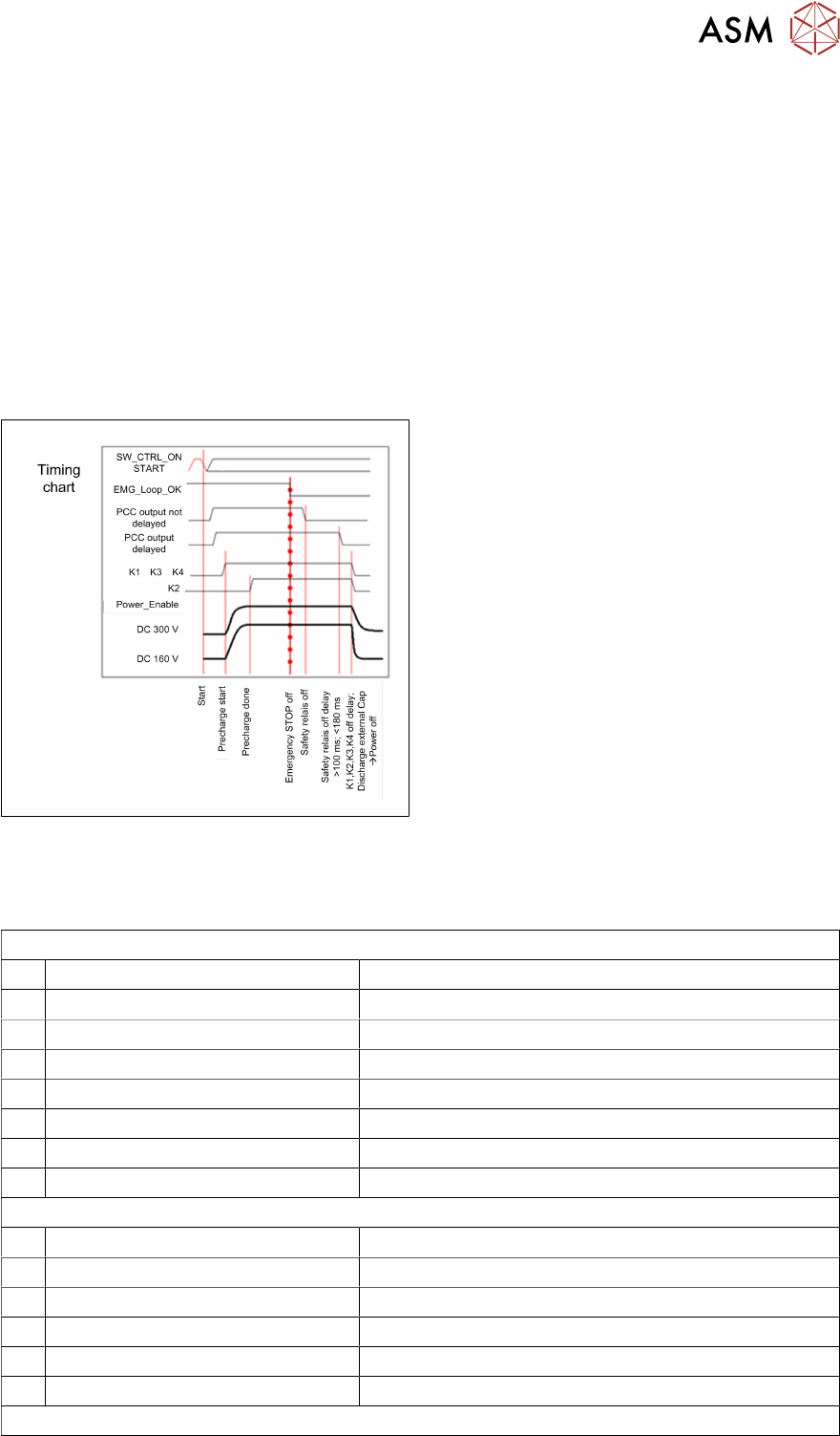
Start sequence:
Rising edge on input “Start” trigger K3.A2 and - if all contactors cut out (Test loop of K5 ok) and no
error from Pre-/discharge monitoring circuit, and all safety loop is close (cover, table E-stop - the
start circuit of the SSK (protective contactor combination K5) K1, K3 and K4 activate without delay
–> 24 V_S and 42V_S are switched on, safety loop closed, charge phase is initiated for the 300V
and 160V voltages (R1 and R2 suppress the charging current). A voltage comparator detects the
end of the pre-charge phase at 300V and 160 V before connects K2 through.
Stop sequence:
After opening the emergency STOP loop, contactors K3 and K4 immediately cut out (42V_S and
24V_S are switched off).
K1 and K2 cut out after the set delay time (T_STOP). The contacts of the de-energized contactors
K3 and K4 discharge the output voltages, together with the discharging resistors R3 and R4..
Due to needs of MGCU (active breaking) stop
category 1 (delayed cut off) is implemented.
Delay time is adjusted at Safety relays and must
be in the range of 140 and 200 ms. Every unit
supplied is adjusted and tested so there are no
adjustments to be done.
7.9 Cable harness interface
Fuse & Distribution Connector Field (FDC)
1. -X5 Mate.-N-Look 9pol FDJ 1&2 DC 27 V
2. -X8 Mini-Mate.-N-Look 6pol DC 24/ 48 V IC & FC-camera
3. -X9 Mini-Mate.-N-Look 6pol DC 24 V/ PCI & Monitor
4. -X14 Mate.-N-Look 9pol Conveyor
5. -X11 Mini-Mate.-N-Look 6pol Trailing interface 1
6. -X12 Mini-Mate.-N-look 6pol Trailing interface 2
7. -X8A Mate.-N-Look 6pol Trailing interface 1 & 160 V
8. -X8B Mate.-N-Look 6pol Trailing interface 2 & 160 V
ELS
1. -CAN1 Sub D 9pol
2. -CAN2 Sub D 9pol
3. -CAN3 Sub D 9pol
4. -CAN4 Sub D 9pol
5. PEMS PEMS
6. -X102 Mate.-N-Look 4pol AC 400 V Power_supply
Distributor Connector Field (DIC)
7 Power Supply
7.9 Cable harness interface
106 Technical Training FSE SIPLACE TX-Series 01/2018
1. -X23 Mini-Mate.-N-Look 15pol Control elements 1
2. -X24 Mini-Mate.-N-Look 15pol Control elements 2
3. -X26 Mini-Mate.-N-Look 12pol Control elements Hood 1
4. -X27 Mini-Mate.-N-Look 12pol Control elements Hood 2
5. -X28 Mini-Mate.-N-Look 15pol COT-insert 1 Signaling & Safety
6. -X29 Mini-Mate.-N-Look 15pol COT-insert 2 Signaling & Safety
7. -X30 Mini-Mate.-N-Look 12pol Control Vacuum_Pump Control Interior light
8. -X31 Mini-Mate.-N-Look 12pol Pneumatic_Main_System
9. -X32 Mini-Mate.-N-Look 9pol Control Vacuum_Pump Control Interior light
10. -X33 Mini-Mate.-N-Look 12pol Reserve I/O & Optional
11. -X34 Mini-Mate.-N-Look 9pol Fan control & monitoring 1
12. -X35 Mini-Mate.-N-Look 9pol Fan control & monitoring 2
13. -X36 Mini-Mate.-N-Look 12pol Security Loop Flap Extension Conveyor
14. -X37 Mini-Mate.-N-Look 15pol Reserve I/O & V3-Connection
15. -X19 Mini-Mate.-N-Look 4pol RS485 FU
7 Power Supply
7.10 I / O Control Unit Distributor
Technical Training FSE SIPLACE TX-Series 01/2018 107
7.10 I / O Control Unit Distributor
X 3 Data Input DI0 to DI7:
DI_0 Safety_Loop_OK "High", when safety loop is closed (all covers,
all tables connected and E-Stop not engaged)
(X22-A3)
DI_1 Reserve (X33-3)
DI_2 E-Stop 2 "Low", when E-Stop 2 is engaged "High", E-Stop not
engaged
(X24-12)
DI_3 Reserve (X31-4)
DI_4 PresSens_PV1Signal from incoming air valve_1. "High": pres-
sure ok.; "Low": pressure too low (<4,5 bar)
(X31-5)
DI_5 PresSens MainValve"High", when the adjusted air pressure
reached
(X31-6)
DI_6 Reserve (X30-4)
DI_7 Reserve
X 4 Data Input DI8 to DI15:
DI_8 Start_Button_1"High" when pressing Start Button 1. (X23-7 / X25-7)
DI_9 Stop_Button_1“High" when pressing Stop Button 1 (X23-8 / X25-8)
DI_10 24V_S "High" when 24V switched status is reached changes from
"Low" to "High when the CSB has the operating voltage and SSK
is activated
(X22-B4 / X25-13
DI_11 Start_Button_2 "High" when pressing Start Button 2 (X24-7)
DI_12 Stop_Button_2 “High" when pressing Stop Button 2 (X24-8)
DI_13 PWR_enabled "High", when the E-Stop circuit is closed, the SSK
is activated and when the safety breakers have been activated
(X22-B3)
DI_14 EMG_Stop_1"Low", when the E-Stop_1 is pressed. Also "High",
E-Stop1 is released
(X23-12)
DI_15 EMG_Stop_Ext option MTC / WPC
X 5 Data Input DI16 to DI23:
DI_16 Button_COTi_2 Signal from Button "COT-Insert"; Location 2.
"High": Button pressed
(X24-9)
DI_17 Hood_2 "High", when the Machine cover _2 is closed "Low",
when Machine cover _2 is open
(K2-A1+ / X25-12
DI_18 Comp_Table_2 "High" when the COT 2 is docked, "Low" when
COT is missing
(X36-2 / X37-13)
DI_19 Hood2_Lock_on "High" Safety switch Hood 2 activated => Cover
cannot be opened
Low": Safety switch Hood 2 not activated => Cover can be
opened
(X27-7)
DI_20 Reserved
DI_21 Reserved
DI_22 Reserved
DI_23 Reserved