00198171-02_Technical_Training_FSE_TX-Series_EN.pdf - 第108页
7 Power Supply 7.10 I / O Control Unit Distributor 108 Technical Training FSE SIPLACE TX-Series 01/2018 X 6 Data Input DI25 to DI31: DI_24 Button_COTi_1 Signal from Button "COT-Insert"; Location 1. "High&q…
7 Power Supply
7.10 I / O Control Unit Distributor
Technical Training FSE SIPLACE TX-Series 01/2018 107
7.10 I / O Control Unit Distributor
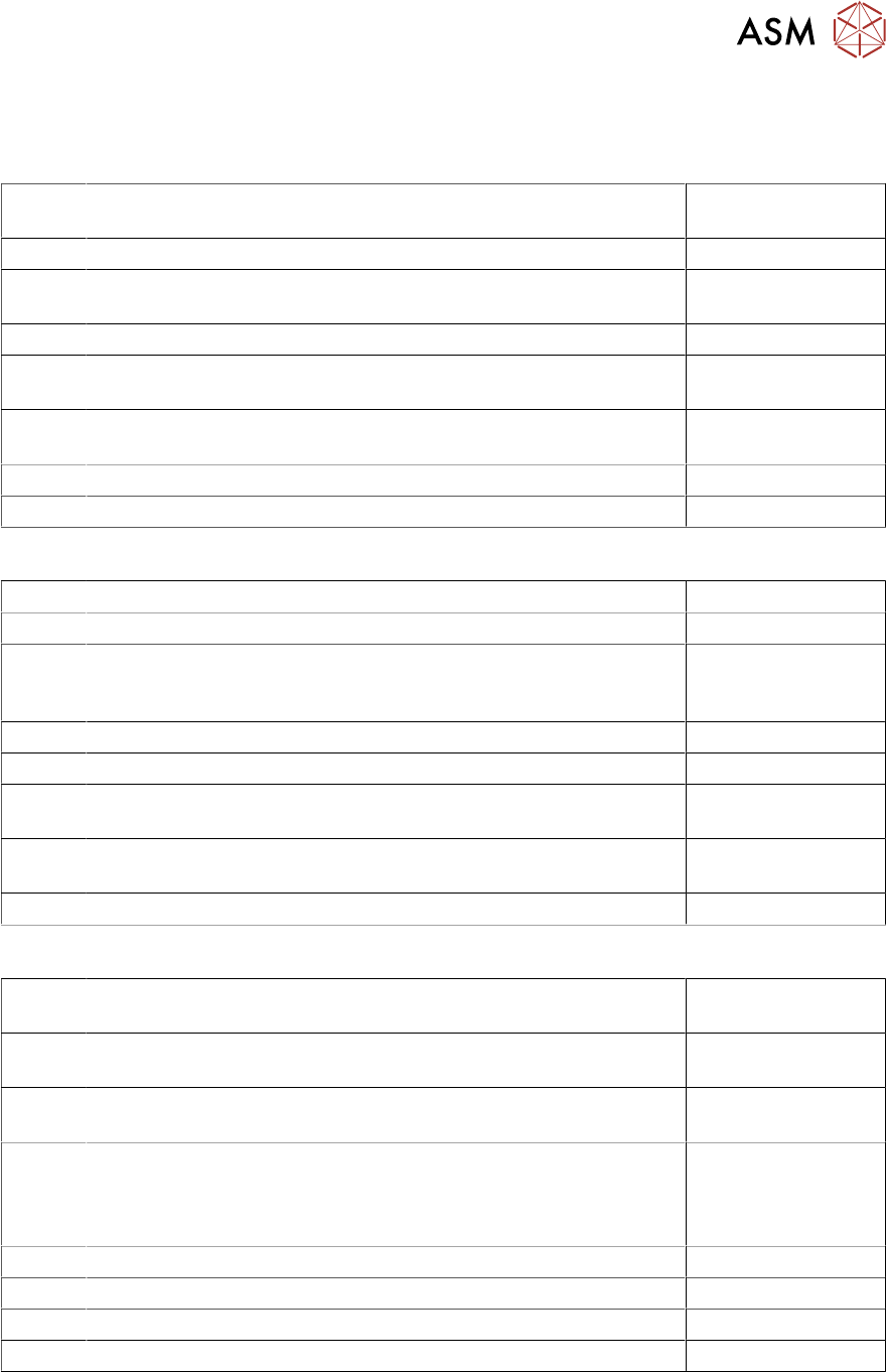
X 3 Data Input DI0 to DI7:
DI_0 Safety_Loop_OK "High", when safety loop is closed (all covers,
all tables connected and E-Stop not engaged)
(X22-A3)
DI_1 Reserve (X33-3)
DI_2 E-Stop 2 "Low", when E-Stop 2 is engaged "High", E-Stop not
engaged
(X24-12)
DI_3 Reserve (X31-4)
DI_4 PresSens_PV1Signal from incoming air valve_1. "High": pres-
sure ok.; "Low": pressure too low (<4,5 bar)
(X31-5)
DI_5 PresSens MainValve"High", when the adjusted air pressure
reached
(X31-6)
DI_6 Reserve (X30-4)
DI_7 Reserve
X 4 Data Input DI8 to DI15:
DI_8 Start_Button_1"High" when pressing Start Button 1. (X23-7 / X25-7)
DI_9 Stop_Button_1“High" when pressing Stop Button 1 (X23-8 / X25-8)
DI_10 24V_S "High" when 24V switched status is reached changes from
"Low" to "High when the CSB has the operating voltage and SSK
is activated
(X22-B4 / X25-13
DI_11 Start_Button_2 "High" when pressing Start Button 2 (X24-7)
DI_12 Stop_Button_2 “High" when pressing Stop Button 2 (X24-8)
DI_13 PWR_enabled "High", when the E-Stop circuit is closed, the SSK
is activated and when the safety breakers have been activated
(X22-B3)
DI_14 EMG_Stop_1"Low", when the E-Stop_1 is pressed. Also "High",
E-Stop1 is released
(X23-12)
DI_15 EMG_Stop_Ext option MTC / WPC
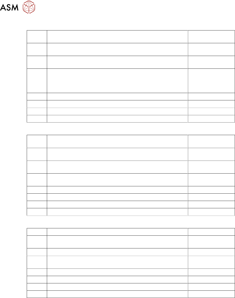
X 5 Data Input DI16 to DI23:
DI_16 Button_COTi_2 Signal from Button "COT-Insert"; Location 2.
"High": Button pressed
(X24-9)
DI_17 Hood_2 "High", when the Machine cover _2 is closed "Low",
when Machine cover _2 is open
(K2-A1+ / X25-12
DI_18 Comp_Table_2 "High" when the COT 2 is docked, "Low" when
COT is missing
(X36-2 / X37-13)
DI_19 Hood2_Lock_on "High" Safety switch Hood 2 activated => Cover
cannot be opened
Low": Safety switch Hood 2 not activated => Cover can be
opened
(X27-7)
DI_20 Reserved
DI_21 Reserved
DI_22 Reserved
DI_23 Reserved
7 Power Supply
7.10 I / O Control Unit Distributor
108 Technical Training FSE SIPLACE TX-Series 01/2018
X 6 Data Input DI25 to DI31:
DI_24 Button_COTi_1 Signal from Button "COT-Insert"; Location 1.
"High": Button pressed
(X23-9)
DI_25 Hood_1 "High", when the Machine cover _1 is closed "Low",
when Machine cover _1 is open
(K1-A1+ / X26-6)
DI_25 Comp_Table_1 "High" when the COT 1 is docked, "Low" when
COT is missing
(X36-2 / X37-13)
DI_27 Hood 1_Lock_on "High" Safety switch Hood 1 activated =>
Cover cannot be opened
Low": Safety switch Hood 2 not activated => Cover can be
opened
(X26-7)
DI_28 Reserved
DI_29 S_Flap EXCo option external conveyor
DI_30 Flap lock on option external conveyor
DI_31 ID EX Co option external conveyor
X 18 Data Input DI32 to DI39:
DI_32 Fan_G1 Loc.1 Input for Fan Control: "Low": Fan Revolution is ok;
"High": Fan Revolution is below the threshold value
(X34-1)
DI_33 Fan_G2 Cover-1 Input for Fan Control: "Low": is ok; "High": Fan
Revolution is below the threshold value
(X34-2)
DI_34 Fan_G3 Loc.2 Input for Fan Control: "Low": Fan Revolution is ok;
"High": Fan Revolution is below the threshold value
(X34-3)
DI_35 Fan_G4 Loc.2 Input for Fan Control: "Low": Fan Revolution is ok;
"High": Fan Revolution is below the threshold value
(X34-4)
DI_36 Reserved
DI_37 Fan Power Supply
DI_38 Reserved
DI_39 Reserved
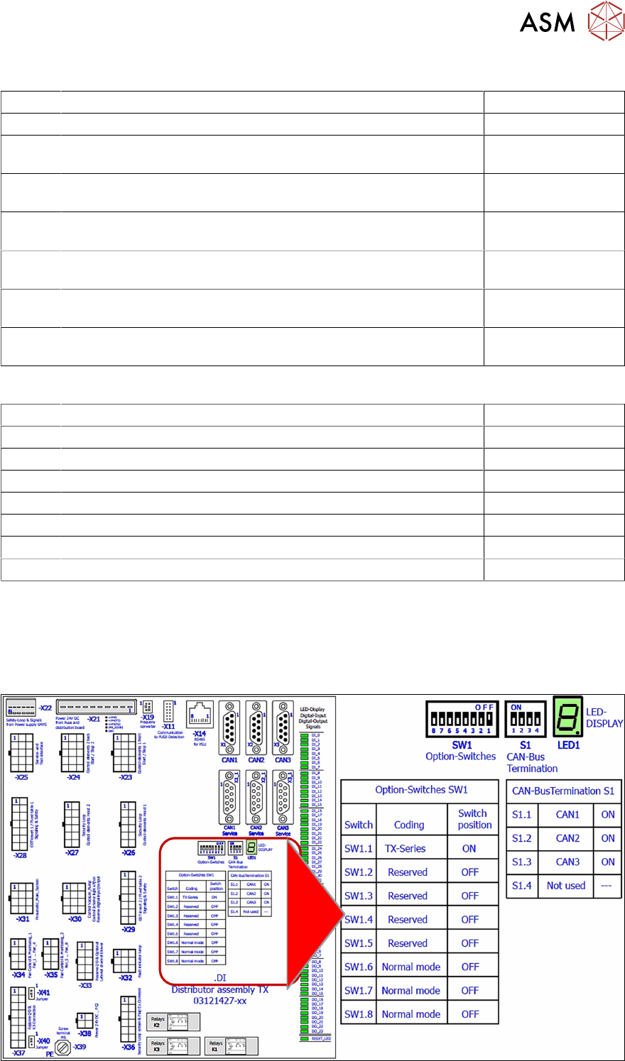
X 7 Data Output DO0 to DO7:
DO_0 Reserved (X37-11)
DO_1 SW_Ctrl_On ("Software release") The machine can only start
when this signal is "High"-Signal (24V OK)
(X23-2 / X24-2
DO_2 Reserved (X31-8)
DO_3 Pressure_PV1 Signal an proportional valve_1. "High": Valve
switches air pressure on; "Low" Valve is not switched
(X31-7 (via R15K))
DO_3 Hood_Lock2 "High" Safety switch locking device an Cover 2 (X27-2)
DO_5 Hood_Lock1 "High" Safety switch locking device an Cover 1 (X26-2)
DO_6 Reserved
DO_7 Interior_light "High"-Interior light ”on” "Low"-Interior light ”off” (X30-7)
7 Power Supply
7.10 I / O Control Unit Distributor
Technical Training FSE SIPLACE TX-Series 01/2018 109
X 8 Data Output DO8 to DO15:
DO_8 Reserved (X37-12)
DO_9 Buzzer (X32-5)
DO_10 Indicator_1_RD Red Light tower_1 lights with “High“ at Port Out-
put
(X32-4)
DO_11 Indicator_2_RD Red Light tower_2 lights with “High“ at Port Out-
put
(X32-9)
DO_12 Indicator_1_GNThe green Light tower_1 lights with “High“ at Port
Output
(X32-1)
DO_13 Indicator_2_GNThe green Light tower_2 lights with “High“ at Port
Output
(X32-2)
DO_14 Indicator_1_YEThe yellow Light tower_1 lights with “High“ at Port
Output
(X32-7)
DO_15 Indicator_2_YEThe yellow Light tower_2 lights with “High“ at Port
Output
(X32-6)
X 17 Data Output DO16 to DO23:
DO_16 Service for integration tests (X25-9)
DO_17 Service for integration tests (X25-11)
DO_18 Service for integration tests (X25-12)
DO_19 Reserved
DO_20 Reserved
DO_22 Reserved
DO_23 Reserved
DO_24 Reserved
Data exchange with the power supply unit SMPS
The interface allows data exchange with the power modules of the SMPS (Switched Mode Power
Supply). For example voltages dips from the customer main net can be seen at the station soft-
ware.
I/O Distributor Assembly DIP Switches